Among the Novice Hams - AC and DC
|
|
Here is a back-to-the-basics treatise on AC and DC, plus an introduction to radio frequencies (RF). The author, Herb. S. Brier, is a licensed Ham who presents a very high level treatment of the topics for rank beginners in this 1957 edition. Remember that Popular Electronics was a magazine intended to appeal to hobbyists with backgrounds in electricity and electronics ranging from knowing how to insert batteries into a flashlight in the proper direction (most of the time) to engineers and college professors. Part of the publisher's mission was to introduce as many aspects as possible in order to capture the interest of as many people as possible. They were pretty successful, based on how long the magazine ran its course. Among the Novice Hams
In discussing the theory behind questions appearing in the FCC amateur license examinations (October and November issues), so far we have made no distinction between direct current (d.c.) and alternating current (a.c.). This is because everything that we have learned up to now is equally true for either type of current. Nevertheless, there are many important differences between the two which must be understood before you can learn much about radio. Anyone who learned how to do long division in school has enough on the ball to master sufficient a.c. and d.c. theory to qualify for an amateur license. So let's get started. The Two Currents. Direct current, as its name implies, always flows in the same direction-from the negative terminal of the power source to its positive terminal. To most of us, flashlight batteries, portable radio batteries, and storage batteries. are the most familiar sources of direct current. Alternating current, however, starts at zero, builds up to a maximum value in one direction, decreases to zero again, builds up to a maximum value in the opposite direction, and again drops to zero. The whole cycle repeats itself over and over many times per second as the terminals of the a.c. generator become alternately positive and negative. The electric power delivered to our homes by the power company is 60-cps alternating current.
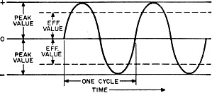
Fig. 1 - The difference between the effective and peak values of an alternating current. Figure 1 shows how a.c. peak and effective voltages differ. The part of the sine curve above the base line indicates that the voltage and the current are building up in one direction (positive), and the part below the base line indicates that they are building up in the opposite (negative) direction. The arrow pointing to the right represents the passage of time. Peak Value = 1.41 x Effective Value Effective Value = 0.71 x Peak Value A direct current has the same effective and peak value. Obviously, if an a.c. generator is connected across a load, such as a light bulb, the current flowing through the load will increase and decrease in step with the volt-age. Consequently, maximum power can flow into the load during only a small portion of each cycle. With d.c., however, full power is delivered to the load constantly. Thus, a direct current of a given voltage will do more work per unit of time than an alternating current of the same peak voltage - exactly 1.41 times as much. But don't jump to the conclusion that the power company is making a 30% profit by selling a.c. instead of d.c. Alternating current is rated in terms of its effective value* - the amount of work it will do in comparison to a unit of direct current. Therefore, one volt (effective value) of sinusoidal alternating current actually has a peak value of 1.41 volts. The effective value and the peak value of d.c. are always equal. Standard a.c. meters are calibrated to measure the effective values of alternating currents and voltages, rather than their peak values. Cathode-ray oscilloscopes show the peak values as well as the actual shape of the a.c. wave. Peak-reading vacuum-tube voltmeters also indicate the peak values. Advantages of Each. The big advantage of alternating current over direct current for utility power is the ease with which it can be sent long distances from the generating plant to the consumer. It can be generated and distributed to strategically located substations at very high voltages - approaching a million volts in some installations. This means that every ampere of current represents thousands of kilowatts of power. As it is the amount of current to be carried that determines the size of wire that must be used in a transmission line, this high-voltage distribution permits carrying a maximum amount of power on a given size of conductor. * Also called the root-mean-square (r.m.s.) value after the mathematical method of computing the effective value.
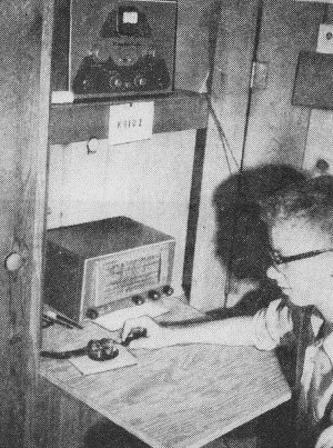
When Al, KN9IDZ, finishes an operating session, he folds up the desk leaf and closes the door of his built-in wall cabinet, concealing his equipment. At substations, the extremely high voltages are stepped down in huge transformers to a few thousand volts and transmitted to neighborhood "pole" transformers, where they are reduced to a safer 117 or 235 volts before the power is delivered to the individual customers. Such voltage division is possible because passing a.c. through a heavy-duty type transformer very slightly affects the amount of power available. It simply changes the ratio between the current and the voltage. Thus, when the voltage is stepped down, the current available is increased, and vice versa. In contrast to a.c., once d.c. is generated at a given voltage, it is impossible to change that voltage with something as simple as a transformer. You can reduce both d.c. and a.c. by passing the current through a resistance, but this just wastes the unused power. To raise or lower d.c., you can use the current to drive another motor-generator (or dynamotor) to generate the desired new voltage. You can also convert it to a.c.-step it up or down to the desired value-and then convert it back to d.c. Both systems are used to power mobile radio equipment from an automobile storage battery. In vibrator-type power supplies, for example, the vibrator, which is actually a vibrating switch, reverses the connections between the battery and the primary winding of the power transformer 100 to 200 times a second, thereby converting the d.c. from the battery to a.c. in the transformer, although not the sine wave a.c. shown in Fig. 1. This a.c. is then stepped up to the desired voltage in the transformer and reconverted to d.c. to power the radio. The higher power requirements of mobile transmitters are often taken care of by dynamotors driven by the battery and delivering 400 to 1000 volts, d.c. Radio Frequencies. All radio signals are alternating currents which differ from 60-cycle power in frequency and in the fact that they are generated electronically in vacuum-tube oscillators, built up by r.f. power amplifiers, and maybe modulated. Amateur transmitters emit signals of frequencies between 1,800,000 cps and 148,000,000 cps and higher. It is the rapidity with which they oscillate back and forth that makes them capable of being radiated into space from an antenna and of travel-ing great distances before being intercepted by a remote receiving antenna. (Just for the record, signals with frequencies as low as 10,000 cycles can be radiated, but it takes antennas several miles long to do the job.) Also, tremendous amounts of power are required to span even moderate distances at such low frequencies, while low-power high-frequency transmitters are capable of sending a signal around the world under favorable conditions.
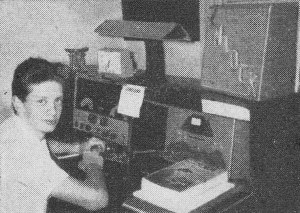
Jim, KN1DCK, Fort Devens, Mass., with his Hallicrafters S85 receiver and Heath DX-35 transmitter. Frequency and Wavelength. Electrical waves travel through space with the speed of light-186,000 miles or 300,000,000 meters per second. Consequently, the distance that a radio wave will travel in the time it takes for it to go through a complete cycle is equal to the distance traveled divided by the number of cycles, or: wavelength in meters = 300,000,000/frequency in cycles. As radio frequencies are usually given in kilocycles (thousands of cycles) or mega-cycles (millions of cycles), the formula is often written: wavelengthmeters = 300,000/ freq.kc.; or wavelengthmeters = 300/freq.mc. Conversely, freq.cycles = 300,000,000/wavelengthmeters. Substituting a few figures in the formulas reveals that a 3750-kc. signal has a wavelength of 80 meters, a 7000-kc. signal have a wavelength of 42.86 meters, and a 15-meter wave has a frequency of 20,000 kc. This relationship between the frequency and the wavelength of a radio signal is of great practical importance in designing transmitting antennas, which must be of a certain length* for best results for a given frequency. Also, it is important that any-one planning to take an amateur examination be able to determine frequency when wavelength is given, and vice versa, because all classes of amateur examinations contain questions requiring knowledge of this kind. * Usually an integral multiple of an electrical half-wave-length.
Posted July 5, 2022 |
|