What is Q? |
|
'Q' is an often used term to describe the elctrical 'quality' of a circuit or component, and for the most part anyone engaged in the conversation (verbally or via reading) understands the concept. However, having a firm grasp on the technical ramifications is required if you happen to be a circuit or system designer and need to conform to certain specifications. 'Q' can be good or bad, depending on your needs. If, for example, you need a narrowband receiver to reject adjacent signals or you are designing a high stability and spectrally clean oscillator, then you want all the 'Q' you can get. On the other hand, if your goal is to receive a spread spectrum signal or generate white noise across some bandwidth, then a lower 'Q' is what you want. This article provides a brief look at 'Q' in series and parallel circuits and relates it to energy stored in the circuit versus energy dissipated. BTW, 'Q' is also used in mechanical and optical system descriptions. What is Q? By Joseph Tusinski, Senior Technical Instructor,| Technical Institute, Norfolk College of William and Mary A review of an important circuit concept for the technician who wants to brush up on his theory.
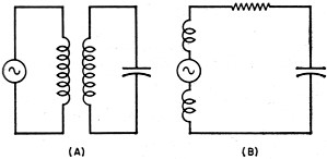
The concept of "Q" is probably one of the most misunderstood in electronics and yet it might be considered just as important as Ohm's Law. The average technician will state that it is a "figure of merit" or possibly the ratio of inductive reactance to the resistance of a circuit. The first definition is, of course, true in all situations; however, the second definition will hold only for a specific case. The restrictive definition of "Q" is brought about by the early training a technician receives in the study of tuned circuits. In this study the resistance of a circuit is distributed in the inductive branch of the circuit, as shown in the equivalent circuit of Fig. 1B. This is normally the condition that would exist in a conventional tuned circuit, and other possibilities that could exist are disregarded either temporarily or permanently. The resistance is depicted as a lumped unit in series with the remainder of the secondary series-resonant circuit. The secondary is considered a series-resonant circuit by virtue of the induced voltage, which is considered to be in series with the inductance. Energy & Power If we may think of "Q" in terms of the energy-storing ability of a circuit instead of XL/R, then a feeling for what "Q" actually means will result. It may be stated that "Q" is a ratio of the energy stored in the circuit to the energy that is being lost in the circuit. The power that is lost is usually in the form of heat. The reader may have noticed the use of the words "power" and "energy" in the preceding statements. It should be remembered that energy is the ability to do work; whereas power is the time rate of doing work. The reactive elements have the ability to do work if some load (resistive) is applied to them. The resistance of the circuit dissipates this energy in the form of heat, i.e., the energy lost is the power it takes to produce the heat. When dealing with very low voltages this heat, of course, is of a magnitude that may not be felt with the fingers. Referring to Fig. 1B, it is obvious that the only factor common to all of the elements in the circuit is the current, where the voltage is in series with the circuit. Then applying our definition to the circuit we may say that the "Q" of the series circuit is the ratio of the reactive power to the real power or "Q" = reactive power/real power.
Fig. 1 - Tuned circuit and its equivalent. The reactive power may be expressed as I2XL and the real power may be expressed as I2R for the inductive branch. The "Q" of the capacitance branch may also be stated as I2XC/I2R, but in this case the resistance of the capacitive circuit at the lower radio frequencies may be considered zero. Therefore: "Q" = (I2XL) / (I2R) = XL/R and: (I2XC) / (I2R) = XC/R = ∞. It can be seen that the expression is the very familiar XL/R, but what about the capacitive element? Actually this situation may be likened to two resistors in parallel. This is shown in Fig. 2. The "Q" of the capacitive branch is considered to be infinite at the lower frequencies where the resistance of the circuit is low. The "Q" of the inductive branch is considered to be finite and therefore is the controlling factor in respect to the energy-storing ability of the circuit.
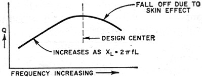
Fig. 2 - Parallel-circuit equivalents. Let us now examine the case of a parallel circuit in which the voltage is applied across both Land C. Let us assume that the resistance of the circuit appears in parallel with the circuit as shown in Fig. 2B. In this case, the resistance of the inductor, which is still present, will be considered to absorb negligible power compared to that absorbed by the parallel resistance. This time the voltage is common to all elements of the circuit and we will use E2/Rand E2/X to determine the power and "Q" of the circuit. In this case, either XL or XC may be used to determine the reactive power (energy) for in a resonant circuit the total energy is either stored in the magnetic field of the inductor or one-half cycle later it will be all stored in the electric field of the capacitor. Then: "Q" = reactive power/real power = (E2/XL) / (E2/R). Inverting and then multiplying, "Q" = (E2/XL) x (R/E2) = R/XL. From this result it may be seen that the definition stated earlier for the case of a series resistor is just the inverse of the definition developed for the case of a parallel resistor. Note further, that for maximum "Q", the resistor value should be as low as possible in the series case and as high as possible in the parallel case. The "Q" of a circuit may be determined by measuring its effectiveness in a circuit. A high-"Q" circuit will respond very sharply at its resonant frequency and the voltage or current will be "Q" times the applied voltage or current. Typical values of "Q" may average about 100 at the lower frequencies, and may reach 300 or more in some transmitter tank circuits. One reason for the higher "Q's" in transmitter tank circuits is the use of large conductors which have a lower a.c. resistance. The "Q" of a typical resonant circuit may vary over a band of frequencies as shown in Fig. 3.
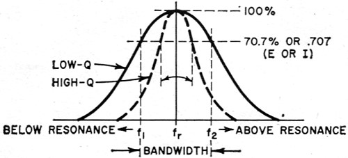
Fig. 3 - Variation of "Q" with frequency. As mentioned, the "Q" may be determined by a measurement of the circuit response, that is, how sharply the circuit responds at its resonant frequency. The "Q" may be determined by measuring the half-power (-3 db) response of a circuit, i.e., where the current or voltage of the circuit drops to 0.707 of the current or voltage at resonance. Between the half-power points a certain range of frequencies has been covered and, by definition this is termed the "bandwidth" of the circuit. This is shown in Fig. 4.
Fig. 4 - Higher "Q's" mean narrow bandwidths. From the response of the circuit, the "Q" may be expressed as: "Q" = resonant frequency/bandwidth or "Q" = fr- / (f2 - f1)· For example, if a circuit would be assumed to be tuned to 1000 kc. and the half-power points were measured at 1005 kc. and 995 kc., the "Q" of the circuit would be: 1000 / (1005 - 995) = 1000 / 10 = 100. A great number of commercial "Q" meters base their operation on this simple fact, while others work on a pre-calibrated method of measuring the degree of response of a circuit or component on the resonant rise of voltage appearing across the circuit or component.
Posted March 9, 2015 |
|