Understanding Frequency-Control Crystals
|
|
Even in this era of incredibly complex electronics, nearly every communications circuit, whether analog, digital, or a mix thereof has a crystal oscillator somewhere at its heart. Technology has advanced significantly in the design and manufacture of crystals, but fundamentally the key parameters of center frequency, phase noise, stability over temperature and time (aging), susceptibility to microphonics effects and magnetic fields, etc., are the same. This article is a good primer on crystals that explains how they work and how they are used. Understanding Frequency-Control Crystals By R. L. Conhaim
One of the most common, yet least understood components of modern communications equipment is the frequency-determining quartz crystal. Deceptively simple in appearance, this remarkable device is responsible for the ability to maintain precise control of radio frequencies of transmitters and receivers in the crowded communications bands. Without this quality, frequency tolerances could not be met, with the result that thousands of users of radio communications would either be denied use of radio or forced to put up with constant interference from other stations. That the crystal is grossly misunderstood is amply demonstrated by users, designers, and writers. Uninformed users, such as many Citizens Band operators, will interchange crystals among different circuits without realizing that this may affect the crystal frequency. Designers often make modifications in crystal oscillators, then appear befuddled by resulting changes in frequency. And writers often treat the "crystal oscillator" as though there were only one such named device, when in fact, there are many basic types, and hundreds of modifications of these. Obviously, one article can't fully explore crystals as used in communications equipment, but perhaps such an article can clear up some of the misunderstandings and cover some of the basic considerations which affect communications users and those who service the equipment. The Crystal
Fig. 1 - (A) shows the equivalent circuit of a quartz crystal, (B) is a Miller oscillator, and (C) is a Pierce oscillator. In communications equipment, the crystal is used in receiver and transmitter oscillators for the purpose of frequency control. It is also used in some equipment in the form of crystal filters to increase the selectivity of receivers but, for the purpose of this article, we'll confine ourselves to crystals as used in oscillators. The quartz crystal is one of a number of substances that exhibit the piezoelectric effect. The word "piezo" is derived from Greek and means "pressure." Simply, the piezoelectric effect is the interaction between electrical voltage and mechanical stresses. Thus, a crystal can produce a voltage when subjected to certain mechanical stresses, or conversely, undergo mechanical stresses when subjected to a voltage. So, if we plug a quartz crystal into an oscillator designed for its use, the voltage present causes mechanical vibration at the particular frequency for which the crystal was designed. In such use, the crystal is behaving like a tuned circuit and, in fact, can be represented as a tuned circuit as shown in Fig. 1A. Here we have the elements of capacitance, inductance, and resistance, represented by the symbols C, L, and R. In addition, we have the capacitance Co, which represents the electrostatic capacitance between the crystal electrodes, when the crystal is not vibrating. The series C, L, and R, are sometimes referred to as the motional- or series-arm elements. Values of L are related to the physical mass of the crystal, those of C to the elasticity or flexibility of the crystal, and R to the heat-dissipating ability during vibration. As a tuned circuit, the crystal possesses an extremely high "Q" - as much as 30,000 to 100,000 or more when connected in the appropriate circuit. Perhaps the most commonly misunderstood fact about a crystal is its ability to oscillate at different frequencies, depending upon circuit configuration and constants (See the impedance-frequency curve shown in Fig. 2). Crystal Resonance
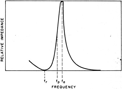
Fig. 2 - The simplified impedance curve of a typical quartz crystal where f, is resonant frequency at series resonance, fr is anti-resonant frequency at parallel resonance, and fp is the practical parallel-resonant operating frequency. A crystal will normally operate at its series-resonant frequency, fr and at higher frequencies up to its anti-resonant frequency fa, depending upon the type of circuit in which it is an element. The difference between these two frequencies may be relatively small in normal terms, but when we consider the tolerances required in communications work, the differences are considerable. For example, a typical 10-mc. crystal may have a series-resonant frequency of 10 mc., and an anti-resonant frequency 16.9 kc. higher than 10 mc. The higher the frequency of operation, the greater the frequency spread between these two points. As a matter of practicality, crystals are not operated at their true anti-resonant frequency, because with a tube circuit shunted across the crystal, there exists a condition where the entire circuit is relatively insensitive to small frequency changes resulting in instability at the region of anti-resonance. In practice, parallel-resonant circuits are operated at a frequency somewhat below anti-resonance, but the difference between this operating point and the series-resonant frequency is still considerable - typically, as much as 5 kc. or more for the 10-mc. crystal just discussed. Thus, rather than considering a crystal as a generator of a precise frequency, it is more accurate to consider it as a device that determines the limits within which the frequency may be varied. It is primarily the parameters of the external circuit in conjunction with the equivalent inductance, capacitance, and shunt capacitance of the crystal and its holder that fix the exact frequency of operation of a particular crystal. Fundamental and Overtone Crystals
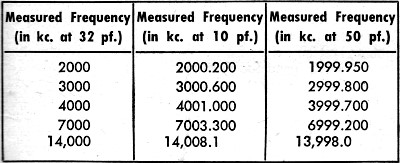
Source: International Crystal Company Table I - Relationship between operating frequency and the capacitance of the oscillator circuit in the equipment. The fundamental frequency of a crystal may be considered as the lowest frequency at which the crystal will oscillate for normal modes of operation. Fundamental-type crystals are also used in harmonic oscillators in which the circuits are specifically designed for such operation. The harmonic frequencies are exact multiples of the fundamentals. For example, a 10-mc. fundamental crystal in a correctly designed oscillator may be made to produce a 20-mc. second harmonic, a 30-mc. third harmonic, and other multiples of the fundamental. Some oscillators are designed to produce many harmonics, although for communications purposes, the design of the oscillator is such that only the particular harmonic desired is produced in any strength. By special processing, a crystal can be made to operate at what is known as an overtone frequency. The term "overtone" as applied to crystals is somewhat confusing, because it does not coincide with the definition as used in musical terms. In music, the first overtone is equivalent to the second harmonic of a fundamental tone. But in crystal parlance, the term overtone is used to designate a frequency approximately, but not exactly, the same as the equivalent-order harmonic. Thus, the third overtone of a crystal is approximately, but not exactly, the same as the third harmonic. Such a crystal is ground for its exact overtone frequency, within specified tolerances, for the oscillator in which it is to be used, rather than being ground for fundamental frequency. The third, fifth, and seventh overtones are the most commonly used in communications work, and permit operation at higher frequencies than would be possible with a fundamental crystal. While the fundamental crystal could be multiplied by additional circuitry, ,the overtone crystal operates directly at the designated overtone in an oscillator circuit, without additional multipliers. It is important to note that an overtone crystal does have a fundamental frequency, and can operate at that fundamental frequency in a properly designed circuit, but the fundamental will not be an exact submultiple of the overtone. Some crystal testers, employing untuned oscillators, actually test overtone crystals in their fundamental mode but these tests are for activity rather than frequency.
Fig. 3 - Typical crystal geometry. (A) shows the axes of an uncut crystal, (B) is the thickness-shear mode of vibration, (C) is the orientation of an X-cut crystal, while (D) shows orientation of a Y-cut crystal. Other cuts are available. Fundamental-type crystals are the preferred types in FM transmitters where both the carrier frequency and deviation can be multiplied simultaneously in subsequent multiplier circuits. Both fundamental and overtone crystals are used in aircraft transmitters, the overtone being preferred where simplicity of circuitry is desired. In such cases, the overtone is also multiplied, but requires less multiplication than would a fundamental-mode crystal. The overtone crystal is also widely used in Citizens Band transmitters and in receivers for most communications bands. In most communications work, the parallel-resonant circuit is employed. In this circuit, the crystal is operating above its series-resonant frequency, fr, and somewhat below its anti-resonant frequency, fa. For such circuits, crystals must be ground for operation into a given external circuit capacitance. In most applications, this capacitance is nominally 32 pf. If the external circuit capacitance differs from that for which the crystal was ground, the frequency of operation will change, as shown in Table 1.
As can be seen from the table, the higher the frequency of operation, the more important becomes the factor of external circuit capacitance, and the greater the frequency error when circuit capacitance is not standard. If circuit capacitance is incorrect, there is a definite probability that the crystal cannot be brought to correct frequency by circuit adjustment, and may even cease to oscillate as the circuit is being adjusted. The circuit shunt capacitance includes the internal capacitances of the tube, capacitors in the circuit, and wiring capacitance. The latter is especially troublesome in Citizens Band units which have been altered by the addition of crystal banks, not properly designed for the equipment. In such cases, crystals which operated within tolerance in the original circuit, may operate several kc. from desired center frequency when plugged into such "outrigger" crystal banks, due to the additional capacitance introduced by the wiring and location of most switchable multi-crystal banks. Typical Circuits
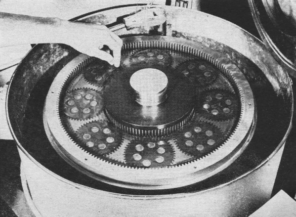
Fig. 4 - Forty-eight crystal blanks can be lapped at a time. Most communications equipment employ parallel-resonant types of crystal circuits. The two most popular types are the Miller circuit, shown in Fig. 1B and the Pierce circuit shown in Fig. 1C. The Miller circuit is basically the tuned-grid, tuned-plate type of oscillator, in which the tuned-grid circuit is replaced by the crystal. This circuit is usually used with overtone crystals, because the correct mode of operation can be assured by tuning the plate-resonant circuit. The Pierce circuit, which is basically a Colpitts oscillator, does not normally rely upon tuned elements in the circuit, other than the crystal. This is a distinct advantage in multi-channel equipment where only the crystal need be changed without the necessity of circuit tuning. However, should the crystal tend to oscillate in more than one mode, an undesired mode of higher activity may control the frequency of operation. There are literally hundreds of variations of the basic Miller and Pierce circuits - so many, in fact, that it is often difficult to determine the basic type of circuit being used. One rule of thumb, which is not always accurate, is this: if one end of the crystal is at the same r.f. potential as the plate, or in some cases the screen, the circuit is probably a Pierce; if one end of the crystal is at the same d. potential as the cathode, it is probably a Miller. Series-resonant circuits are sometimes employed, especially with fifth- and seventh-overtone crystals and in standards and measuring equipment, because of the excellent stability inherent in such circuits. However, these circuits are relatively complicated, often employing either multiple tube configurations or bridge circuitry. Typical series-resonant circuits include the Butler oscillator, capacitance-bridge oscillator, the Meacham bridge, and many others, some of which are quite complex. In all these circuits the crystal is designed to operate at series-resonance, in which crystal impedance is very low, and external circuit constants are of less importance in controlling the frequency of operation. Crystal Cuts
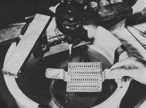
Fig. 5 - Crystal blanks are etched to prevent aging and drift. The exact physical manner in which a crystal vibrates is dependent upon the way it is cut from the basic quartz as shown in Fig. 3A. Different vibration modes have different characteristics. In most communications work, the preferred mode of vibration is the "thickness shear" (Fig. 3B) in which the applied voltage tends to "shear" or distort the crystal along its thickness. The crystal blank is cut from the basic quartz according to the characteristics desired. A "mother" stone of quartz has three basic axes, designated X, Y, and Z. The X axis intercepts opposite angles of the six-sided-stone, as shown in Fig. 3C. The Y axis (Fig. 3D) intercepts opposite sides of the stone. The Z axis runs longitudinally through the stone. An X-cut crystal has its faces perpendicular to the X axis, while the Y cut faces are perpendicular to the Y axis. In the early days of crystal usage, the X and Y cuts were the only ones used. But these types of cuts have certain disadvantages among which is their tendency to change frequency with changes in temperature. Modem communications equipment requires highly stable operation and to meet these requirements, new types of cuts were devised in which various angles of rotation of the plate around one, two, or even all three axes are employed. The most popular cut in communications is the AT cut. It may be oriented to give a zero-temperature coefficient (that is, no change in frequency) at anyone of a number of different temperatures. Some are designed for room temperature operation and are adequate for base-station operation. Others are designed for use in crystal ovens maintained at some specific temperature such as 85°C or 75°C. These are used in mobile equipment where widely varying ambient temperatures can be expected. Others can be oriented to show a reasonable temperature characteristic over a fairly wide range of temperatures, and are used in aircraft equipment, Citizens Band transceivers, and similar equipment where frequency tolerance does not require the use of a constant-temperature oven. Crystal Manufacture
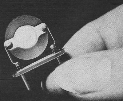
Fig. 6 - Communications-type crystals are usually edge-clamped. Although the crystal is a relatively simple-appearing device, its manufacture requires a high degree of precision. Quartz is the basic material, although other substances have been used for oscillator applications. The raw quartz is silicon dioxide, a hard, glass-like, six-sided prism whose chief source of supply is Brazil. Quartz crystals as they exist in natural form are subject to many imperfections and structural faults and before a stone can be used for radio crystal manufacture, it must be examined for suitability, by using normal or polarized light. In addition, the optic or Z axis is determined by visual inspection or by the use of optical methods. The crystal is then marked for cutting into crystal blanks. Processing of the crystal blank usually begins with a lapping operation, as shown in Fig. 4 in which a number of blanks are lapped at the same time. Crystals are lapped and polished to a frequency slightly higher than the desired frequency. Crystals designed for overtone operation may be polished to a finer finish than that required for fundamental operation. After lapping and polishing, the blanks are chemically etched as shown in Fig. 5. The etching process helps to prevent the crystal from aging and drifting in frequency after the crystal is processed. In many communications applications, electrodes are plated directly on the crystal blank. Plating may be done by chemical deposition, evaporation under vacuum, sputtering or furnace-firing using silver or gold paints. The plating serves to bring the crystal to final frequency, and the frequency can be controlled to very fine limits by the thickness of the plating. After plating, the crystal is mounted on a base. Although a variety of mounting techniques. are employed in crystal manufacture, communications types are usually edge-clamped as shown in Fig. 6, using wire spring loops which serve both to hold the crystal and make electrical contact. The blank, mounted on its base, is then calibrated to its final frequency after which the covering can and base are soldered together. In some cases, the entire unit is evacuated and either sealed off under vacuum, or filled with dry nitrogen which serves to prevent aging due to the presence of moisture. Crystals are then subjected to a number of checks which may include testing under a variety of temperature conditions and in oscillators which are exact electrical duplicates of those in which the crystal is to be used. Final frequency determination is done with an electronic counter to be sure the crystal will operate within the specified tolerance. The crystal manufacturer will usually have on hand a vast amount of correlation data for all types of commercial communications equipment. For reasons given elsewhere in this article, it is important that the crystal manufacturer has specific and detailed information on the circuit in which the crystal is to be used. Otherwise, frequency tolerances cannot be met. Where crystals are required for home-made equipment such as frequency standards, recommended circuits of the crystal manufacturer should be closely followed. Care of Crystals While the modern communications crystal is a rugged device, care should be used in handling and operating it to assure consistent and uniform performance. The typical AT-cut overtone crystal is only a few thousandths of an inch thick and is subject to damage. You might drop a crystal 15 times without hurting it, but conversely, it might break on the first drop. If you hear things rattling around inside the can after the crystal has been dropped, it should be relegated to the wastebasket. Circuit alterations which result in excessive drive current through the crystal, may also cause the crystal to fracture. Although this is a rare occurrence, excessive drive can also cause erratic operation. Occasionally, you may find a faulty crystal which has a tendency to operate in more than one mode. It may oscillate at two different frequencies simultaneously. In the case of overtone crystals, these two frequencies may be reasonably close together. Other faults include the tendency to change frequency during operation - such crystals should be replaced. Crystals, like any other commodity, come in different qualities. Because of the vital function of the crystal in both communications transmitters and receivers, the safest practice is to buy the best crystal you can afford. Either buy directly from the equipment manufacturer or from a reliable crystal manufacturer, in either case giving all the pertinent data that is required. In so doing, you will avoid the problems encountered with poorly made crystals and you can be sure that your equipment will operate at peak efficiency for long periods of time.
Posted March 6, 2017 |
|

 There are many misunderstandings about quartz crystals, the main
one being that they are always on frequency. A detailed analysis of crystals and their associated oscillators
is covered in article.
There are many misunderstandings about quartz crystals, the main
one being that they are always on frequency. A detailed analysis of crystals and their associated oscillators
is covered in article.