Stereophonic FM Multiplex System |
|
FM radio has been in the news fairly frequently in the last couple years as phone manufacturers and the National Association of Broadcasters lobby the FCC and politicians to mandate the inclusion of FM radio capability into every phone manufactured. In a ploy to exploit the gullibility and egos of said bureaucrats and pols, their primary argument that FM radio is a 'first informer in times of crisis,' assuming of course that people will miss news of 'the big one' when and if it occurs. To my knowledge, successful reception of FM radio on a cellphone requires the listener wear a set of wired ear buds since the wire from the phone to the ear buds functions as the antenna. What percentage of cellphone users would bother to carry a set of ear buds? I, of course, am a huge proponent of the continuance of over-the-air broadcasting, including that of television. However, I also resent the continual manipulation of citizens and implementation of regulations that impose unnecessary financial and inconvenient burdens. Stereophonic FM Multiplex System By Daniel R. von Recklinghausen/ Chief Research Engineer, H. H. Scott, Inc.
Authoritative details on the newly approved method of broadcasting stereo programs over a single FM channel. On April 19th, the Federal Communications Commission issued specifications for the standard of modulation of FM multiplex broadcasts. This decision came after long, careful deliberation and study of many possible multiplex systems. At least 17 different systems were proposed, some of them dating back a good many years. The National Stereophonic Radio Committee, with the help of engineers, members of the Electronic Industries Association, representatives of the Institute of High Fidelity Manufacturers, Inc., as well as other agencies including the FCC, studied all of these systems and narrowed the field to eight systems of six basically different groups. In May 1960, the FCC issued Docket 13506 calling for technical comments and field tests of these systems from the same station. Six of these systems underwent field tests in July 1960, using the facilities of KDKA in Pittsburgh - with receiving facilities at the Uniontown Motel in Uniontown, Pa. Many hours of test recordings were made on tape, along with the measurement of many pertinent parameters. This data, plus an analysis of all aspects of the systems tested, was then submitted to the Federal Communications Commission in the form of a report - as bulky as two New York City telephone directories. System Specifications The system adopted by the Federal Communications Commission is along the lines of the methods proposed by General Electric Company and Zenith Radio Corporation, with certain aspects of the system developed by the FCC. These are the essential specifications of the FM stereo broadcast transmission: 1. The modulating signal for the main channel is the sum of the left and right audio signals. 2. A pilot carrier at 19,000 cycles, ± 2 cycles, modulates the main carrier between 8 and 10%. 3. The sub carrier is the second harmonic of the pilot carrier and crosses the time axis with a positive slope simultaneous to each crossing of the time axis by the pilot carrier. 4. The sub carrier is amplitude-modulated and the subcarrier itself, but not its sidebands, is suppressed to less than 1% modulation. 5. The modulating signal for the sub carrier is the difference of the left and right signals with a frequency response of at least 50 to 15,000 cycles with 75-microsecond pre-emphasis. The main channel modulation, as in present monophonic service, has the same requirement of frequency response and pre-emphasis. 6. The sum of the sidebands resulting from amplitude modulation of the sub-carrier causes a peak deviation of the main carrier of 45% when only the left or right signals are present. The individual maximum modulation capabilities of the main carrier and the subcarrier are 90% since the former reaches a maximum when the latter is zero, and vice versa. 7. The frequency response of the sub-channel is identical to the main channel (including pre-emphasis) to within 0.3 db over the whole frequency range and the phase response must match to ± 3 degrees. This results in a minimum separation of 29.7 db, maintained from 50 to 15,000 cps. 8. The distortion requirements of the subchannel are the same as for the main channel and also for monophonic service. The distortion of the audio equipment in the studio, the transmitter, and its monitor operating together with proper pre-emphasis and de-emphasis networks cannot be higher than 3.5% between 50 and 100 cycles, 2.5% between 100 and 7500 cycles, and 3% between 7500 and 15,000 cycles. 9. Background music operation (SCA) is permitted. However, the background music carrier may not modulate the transmitter more than 10% and the crosstalk from the background music channel into either stereo channel must be at least 60 db down from 100% modulation. Spectrum & Waveforms Fig. 1 shows the spectrum which can be found at the output of the FM detector. In normal monophonic operation of the station, only the main channel and perhaps the additional subchannel for background music is used. For stereo operation, the maximum modulation of the main channel is then reduced from 100% to 90%, causing a volume change of less than 1 db which is inaudible for all practical purposes. In addition to that, the pilot carrier and the subchannel with stereo information is activated. It should be noted that the main carrier of the station is modulated with FM and never with AM. Therefore, all advantages of FM are maintained.
Fig. 1 - The spectrum of signals that is found at the output of the FM detector. The FCC system of stereophonic broadcasting had its inception in a time-division multiplex switching system. Here, the input of a transmitter is switched rapidly between the left and the right stereophonic program channels, switching at a 38-kc. rate. The system was analyzed mathematically and with test equipment. It was discovered that this system was basically a "sum and difference" system. The sum of the left and right stereophonic channels appeared as audio modulation of the main carrier, whereas the difference between the left and right stereophonic channels appeared as suppressed-carrier amplitude modulation of a series of odd harmonics of the switching rate. Since FCC regulations do not permit the radiation of any signals in excess of 75,000 cycles, filtering of the higher harmonics of the switching rate resulted in the adopted system. Fig. 2 shows the waveforms which can be found on the output of the FM detector of a high-quality FM tuner. In this illustration the presence of the pilot carrier has been omitted for the sake of clarity. For example, only the left channel (channel A) is modulated with a sine wave. The sine wave itself will be found if the output of the detector is examined with an oscilloscope and a low-pass filter. The use of a high-pass filter will then show the suppressed-carrier amplitude-modulated subchannel. The elimination of all filters will then show the composite modulation which is the sum of the audio modulation and the subchannel modulation. Here it can be seen that channel A is turned on several times during the complete audio cycle and turned off just as many times. The right channel (channel B) is not modulated.
Fig. 2 - Waveforms at the output of the FM detector with a sine-wave modulation on the left channel. Pilot carrier has been omitted. The left and right channels can carry completely separate and uncorrelated information, which is often true in stereophonic recordings. In Fig. 3, channel A carries the high-frequency audio modulation, whereas channel B carries a low-frequency audio modulation. The summing of both of these modulations results in the main channel modulation which shows the high-frequency sine wave superimposed on a low-frequency sine wave. The subchannel shows the difference of the two modulating wave-forms as the carrier envelope of the suppressed carrier signal. Both the main channel and the subchannel modulations form the composite modulation which now clearly shows the presence of both waveforms. The shaded areas shown in the last two portions of the figure are actually the high-frequency sidebands of the subcarrier.
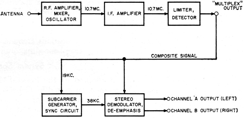
Fig. 3 - Output waveforms with high-frequency audio modulation on channel A, and low-frequency audio modulation on channel B. The new FCC regulations concerning stereo broadcasting became effective June 1st. Because broadcasting equipment is still in short supply and only the major cities are likely to feature multiplex stereo broadcasting, the waveforms described probably cannot be observed immediately. However, since stations presently engaged in AM-FM simulcasting are the ones most likely to carry stereo multiplex broadcasts, a phone call to the station should elicit information as to when stereo broadcasting is likely to start. Receiving Stereo Broadcasts To receive these stereo broadcasts, a multiplex stereo tuner or an FM tuner with a multiplex adapter will be required. Fig. 4 shows a block diagram of a stereo tuner. The signal from the antenna passes through the r.f. amplifier, mixer, and oscillator and is then amplified further in the i.f. amplifier at an intermediate frequency of 10.7 mc. and detected as in monophonic service. For normal monophonic service, the output of the detector is then passed through a de-emphasis network and amplified still further in an audio amplifier. At the output of the FM detector, the composite stereo signal is available. It is then split into two paths, one path containing the 19-kc. pilot or synchronizing carrier. A filter selects this pilot carrier and this block also contains means to produce a 38-kc. carrier frequency to be fed to the stereo demodulator, which also receives the composite signal. After de-emphasis of the left-and right-input signals, further audio amplification is required to give a left and right audio output of sufficient amplitude.
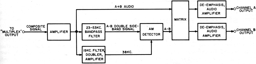
Fig. 4 - Simplified block diagram of a stereo FM tuner that will produce signals for application to a stereo amplifier. Fig. 5 is a block diagram of a multiplex stereo adapter, shown in greater detail. Since the stereophonic system that has been described is a "sum and difference" system, the stereophonic subcarrier may be demodulated by a synchronous detector to recover the difference modulation and the main channel sum modulation may be matrixed at audio frequencies with the conventional circuitry to derive the left and right signal outputs. Here, the composite output signal of the FM detector must first be amplified to overcome the insertion loss of the matrix network and to operate the AM detector at its proper level. The carrier of the AM detector may be provided by selecting the output of this amplifier with a 19-kc. filter, amplifying this signal, and using the second harmonic (38 kc.) as the inserted carrier to the AM detector. The output of the amplifier will also pass through a 23-53 kc. bandpass filter into the AM detector. In this case, the synchronous detector would be a double diode for recovering both polarities of the A - B audio signal which is then matrixed with the A + B audio signal from the amplifier. Both the A - B and A + B signals may contain a de-emphasis network. However, better separation results if the de-emphasis network is placed after the matrix network in the circuit. The matrix network would be nothing but a set of resistors. Further audio amplification is required to give proper audio output.
Fig. 5 - Block diagram of a multiplex stereo adapter showing the circuits required. The synchronous detector could be driven by an electron-coupled 19-kc. oscillator with frequency doubling in the plate circuit so that the 38-kc. reference carrier may be correctly re-inserted in the modulated subcarrier signal. The oscillator synchronization would be accomplished by injecting the 19-kc. pilot carrier into the oscillator tank circuit. It is important that the proper phase relationship between the inserted carrier and the A - B double-sideband signal be maintained. A phase error of 12 degrees can result in separation being reduced to 20 db. An 180-degree phase shift would result in an interchange of the left and right audio outputs. The A and B output signals may also be derived directly in one operation on the composite modulating signal appearing at the composite signal amplifier output. Such a detector would make use of a tube similar to the 6AR8 beam deflection tube. This tube has one control grid, two plates, and two deflecting plates. The reference carrier of 38 kc., derived as above, is applied to the deflecting plates and the composite stereophonic signal is inserted at the control grid. The two plates will have as outputs the product of the reference carrier and the composite signal which is, of course, the left and right signal. The adapters described here are of a rather simple nature. Such adapters would be used where cost is of prime importance and the various aspects of performance are perhaps of a secondary nature, especially as far as ultimate quality performance is concerned. The quality of the FM tuner employed will also affect the various performance aspects rather severely. For example, if it is desired to maintain a 30-db channel separation, then the frequency response of the tuner with the adapter amplifier may not vary more than 3/10 of 1 db from 50 to 53,000 cps, and the over-all phase response from antenna input to stereo detector input may vary no more than ± 3 degrees from a linear phase line over the same frequency range. This performance aspect is considerably more stringent than that required for monophonic operation. The internal impedance of the multiplex output of the tuner and the input impedance of the adapter can affect frequency response severely and, to a greater extent, the phase response if an adapter of one make is used with a tuner of another make. For this reason, the prospective buyer of a multiplex adapter should check with the manufacturer of his tuner as to the type of multiplex adapter to buy and also as to the extent of the modifications required of the tuner to be able to obtain maximum performance. As the block diagram of Fig. 4 indicates, full advantages of FM are maintained since the limiter or limiters in the tuner are in normal operation as in standard monophonic service. The amplitude modulation of the subcarrier is strictly a subsidiary modulation and the output voltage of the subchannel detector will be proportional to the subchannel output voltage of the FM detector in the tuner. Since the main channel output voltage at the tuner may vary with signal strength, the subchannel output voltage will vary as well. Because of the proportionality of output voltages, separation of left and right channels will be maintained irrespective of signal strength and, therefore, no front-panel separation adjustment is required. Such a control may actually be harmful since this control is very likely to be misadjusted by uninformed friends, neighbors, or children and the correct setting can be found only when the test signal is transmitted by the station equipped to broadcast multiplex stereo. A separation control may still be found as a screwdriver adjustment on certain adapters to compensate for tolerances in the matrix network or the subchannel frequency response of the tuner. For the latter deficiency, this control will be quite beneficial in adjusting for good separation at low- and mid-audio frequencies. However, a good high-frequency separation will be obtained only if proper equalizing networks for the tuner's frequency response are used. The characteristics of these networks will vary among different types of tuners. This is one example where the quality of the tuner, along with the quality of the adapter, and the design of both will have an important effect on stereo performance. Background Music Operation As the FCC specifications indicate and as illustrated in Fig. 1, background music operation (SCA) of FM radio stations is still permitted. However, these types of signals will have to be broadcast on a fairly high-frequency subcarrier (such as 67 kc.) when the station is engaged in multiplex stereo operation. The careful design of the stereo multiplex adapter will have a great influence on the amount of interference which will be experienced when such a background music channel is in operation. The transmitter's design and adjustment will also affect this type of interference. However, the maximum transmitted interference (-60 db) is specified by the FCC.
First photo received by the editors of a multiplex adapter designed in accordance with the recently announced FCC-approved system. The unit is the H. H. Scott Type 335, a wide-band self-powered adapter, which is being sold for just under $100. A station not engaged in stereo multiplex may operate its background music carrier or carriers in the band between 20 and 75 kc. It is therefore possible that this type of background music modulation may be picked up by a multiplex stereo tuner. The type of interference which will then be heard can be described as a "swishing whistle," the swishing controlled by the rate at which the background music is performed. Such a noise would be an indication that that particular station has a background music carrier in operation and is not broadcasting stereo. These types of noises are not the fault of the tuner or the adapter. Some Problems The stereo multiplex system adopted by the FCC, as well as any other multiplex system that has ever been proposed, is subject to interference to a greater degree than the monophonic main channel. Ignition noise may perhaps sound louder; stray radiation from FM tuners, TV sets, and other transmitters may cause whistle tones to appear in the background; and the tube hiss of the first stage in the FM tuner will degrade the signal-to-noise ratio. When listening to signals of marginal signal strength, the signal-to-noise ratio of the left- and right-channel stereo output signals will be poorer than the monophonic main channel by approximately 20 db. Measurements agree with this theoretical prediction to within a few decibels. The ultimate signal-to-noise ratio of the left- and right-channel outputs will be well in excess of 60 db. Because of the reduced signal-to-noise ratio when listening to stereo on weak stations, it will be desirable to have a directional outdoor antenna available to provide an increased amount of signal for the tuner. The distortion which will result in a high-quality stereo multiplex adapter connected to a high-quality FM tuner will be on the order of 1/2% to perhaps 1%. This is considerably lower than the distortion in subcarrier detection employing other types of modulation. However, in listening to a station it is possible that considerable distortion may be experienced when listening stereophonically, yet relatively little distortion be present when listening monophonically. This increased distortion may be due to incorrect adjustment of the tuning control of the tuner or more likely is caused by a reflection of the station's transmitted signal from nearby buildings. This is an interfering signal. For this problem, correct adjustment of the tuning control, reorientation of the antenna, perhaps a reversal of the antenna leads, will reduce this type of interference. Tape recorder users will recognize that multiplex stereo broadcasting provides an opportunity to obtain good quality off-the-air recordings. However, during multiplex field tests some of the tape recordings which were made indicated that there could be definite interference problems. This is true since the bias frequency of many tape recorders is not far removed from the re-inserted carrier frequency or its harmonics. In well-designed adapters, these potential problems have been eliminated. Multiplex can be a greater boon for the listener than was the development of the stereo record. The fact that certain problems have been mentioned in this article shouldn't cause too much consternation. You can't get something for nothing. However, with proper thought given to the selection of equipment and care taken in installation, the results should make the effort completely worthwhile.
Posted September 21, 2015 |
|