The SCR Revolution
|
|
Prior to the invention of the silicon-controlled rectifier (SCR), most semiconductor devices were only able to handle powers in milliwatt range, with some reaching into the realm of a few watts or tens of watts. Voltage handling got up to around 1 kV (and 500 A) for diodes and 200 V for transistors. The higher power and voltage devices were exceedingly expensive and were used primarily in special applications. When this article appeared in a 1966 issue of Electronics World magazine and the SCR had been introduced less than a decade earlier, the price of an SCR had dropped from more than $300 to less that 50¢ apiece. Due to the construction of the SCR, it is more robust and can handle high power switching applications (it is generally not used as a signal amplifier). Unlike a triac, which can be controlled with a signal to turn the device both on and off while voltage is present across the anode and cathode, the SCR can only be used to switch off current, and then to turn back on the bias needs to be removed. At that point voltage can be restored and the SCR will conduct again until the triggering signal cuts it off once more. The SCR Revolution
A drastic price decline has opened up many new applications for this semiconductor switching device. By the end of this year, SCR's may represent a $40 million market. This article shows a large number of basic static switching and control circuits. By J. E. Mungenast Semiconductor Products Dept. General Electric Co. In 1957 electronics took a giant step into the broad world of electric control. In that year, the first practical silicon controlled rectifier was fabricated by Gordon Hall of General Electric. This was the first semiconductor that could economically switch kilowatts. The SCR has since grown into a wide family of devices with a potential $40 million market by the end of 1966. Let's examine why it has grown so swiftly and what opportunities it offers to the electronics industry as a whole. The SCR's and their close relative the bidirectional a.c. switches (known variously as Triacs, symmetrical switches, or five-layer switches) are logical extensions of the solid-state rectifier and transistor family. Fig. 1 shows these four basic devices along with some of their characteristics and applications. When the SCR and its thyratron gas-tube counterpart is compared with the transistor and its receiving-tube counterpart, we see that the prime difference is not only the power-handling capability but also the fact that the SCR works in the switching mode only. This is the key to its power-handling capability - but it can cause some inconvenience on direct-current circuits, as we will see later. The second valuable SCR attribute is its extraordinary sensitivity. Again, like the thyratron, it offers a degree of power amplification that makes possible inexpensive, simple control circuitry triggered by a number of sensors, such as photocells and thermistors.
Fig. 1 - Four basic semiconductor devices along with their main characteristics and their applications.
Three members of the SCR family showing the very wide range of currents and voltages. The large assembly is a water-cooled a.c. switch that will handle up to 1200 amps at 1800 volts peak. The small unit at the left is the new, inexpensive plastic-encapsulated SCR with a current rating of 2 amps at 200 volts peak. The small unit at the right is a bi-directional switch (Triac) with a 10-amp, 400-volt peak rating. Additional SCR's are shown in the cover photograph.
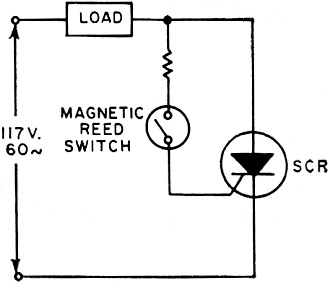
Fig. 2 - Simple static-switch SCR circuit.
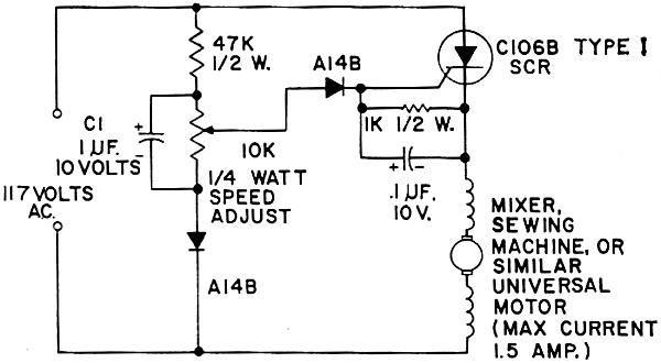
Fig. 3 - A popular variable speed control circuit using SCR.
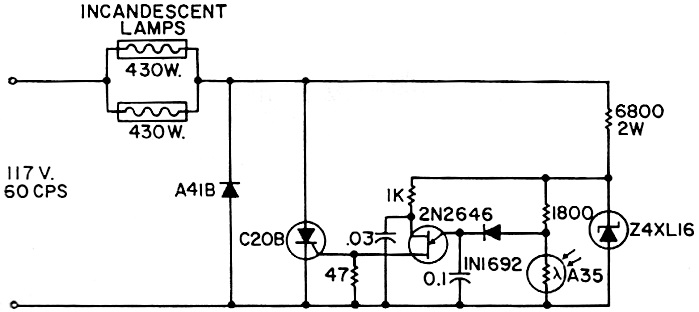
Fig. 4 - High-gain limited-range light control circuit with unijunction transistor. For applications in which control of the load below the half-power point is not required, a rectifier can supply a half cycle uncontrolled, and an SCR can provide regulation by phase control during the other half cycle.
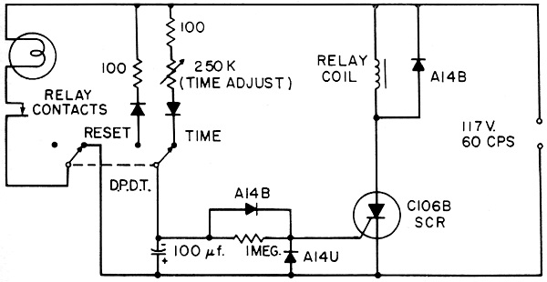
Fig. 5 - Time-delay relay circuit for enlarger, patio light, or garage light. Circuit can be used to turn off lights after an interval of up to about 1 minute. The SCR supplies enough current to energize a low-cost relay coil. The SCR is triggered by only a few microamps of current from the RC network. Note: All Resistors 1/2 Watt
Fig. 6 - Full-wave control circuits using SCR's and Triacs.
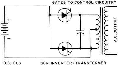
Fig. 7 - SCR inverter circuit changes d.c. to higher voltage a.c.
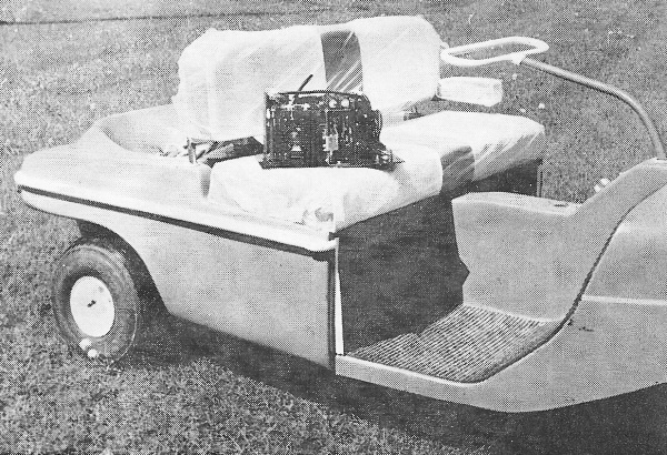
This golf cart employs SCR's for speed control. The entire electronic package with the throttle rod coming out of the top of it has been removed and placed on the golf-cart seat.
Fig. 8 - "D.c. transformer" or "chopper" battery motor drive.
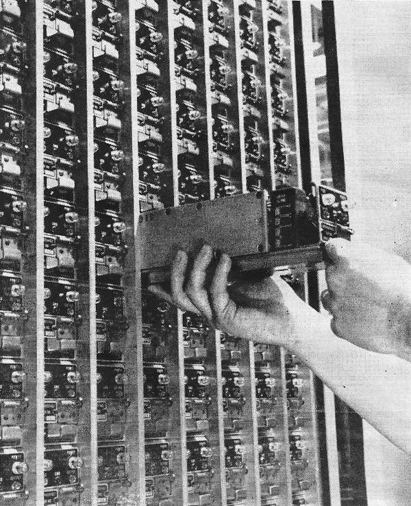
A bank of 500 SCR inverter modules, each producing kilowatts of power, are connected in parallel to produce almost a mega-watt of ultrasonic power for a particular military application.
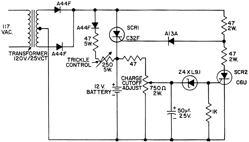
Fig. 9 - A 15-amp SCR-based battery-charging regulator which cuts down the high charging rate to a trickle charge at a preset level. Thus, the SCR will play an important role in automotive applications, as for example in electronic ignition systems or in electric windshield wiper controls. It will be used in the appliance field for varying the speed of motors and for varying the brightness of lamps. It will be found in the toy/hobby market where its sensitivity will make possible unique control schemes such as for model trains. The cover photograph, as well as the one in this article, show some members of the SCR family. Note the wide range of size and operating characteristics. Also note particularly the tiny new plastic-encapsulated SCR. This device has an instantaneous power gain of over one million, yet it costs only 35 to 50 cents in large quantities. Like most semiconductors, the SCR has been characterized by a precipitous price decline. The first units in 1957 cost about $325 each. Today a comparable unit costs less than $2.00. The SCR is in itself of little use; auxiliary circuitry is necessary to accomplish the desired function. The main circuits that form the basis for many of the thousands of SCR applications of today and tomorrow are discussed below. The Static Switch Fig. 2 shows the simplest form of the half-wave static switch using a magnetic reed switch for energizing the gate circuit of an SCR. Note that the SCR fires, or latches into conduction, whenever gate current is allowed to flow through the reed switch. This can be actuated either by a permanent magnet, making a proximity switch, or by passing current through an electromagnet coil. The wide range of uses includes simple explosion-proof switches (there is no arcing mechanism and no fumes are entrapped, as the semiconductor and reed switch are mounted in a plastic block), relay replacement where highly repetitive operations are needed, and sensitive relay replacement where an SCR amplifier in conjunction with a rugged, inexpensive power relay does a more reliable, economic job than a delicate sensitive relay. Phase Control But the most promising family of applications for the SCR's involves phase control, whereby the load is switched on and off at certain times in the applied a.c. cycle, thereby metering the power to the load. The basic principles of operation have been described many times in past issues of this publication, so they will not be repeated here. Fig. 3 shows one of the most popular circuits, the series motor speed control. For many years, tool and appliance manufacturers have sought a way not only to adjust the speed of the series motor but, more important, to furnish governor action that would maintain the necessary torque, even at the low-speed settings. This is accomplished in the circuit shown in Fig. 3. Essentially the SCR performs three functions here: first as an on-off switch, second as the means for voltage reduction, and third as the sensing mechanism making feedback control possible. The counter-e.m.f. of the rotor gives us a tachometer indication of speed which is compared with the desired setting of the speed-adjust potentiometer. Any differential then varies the phase angle to maintain the necessary speed. Thus, both the sensitivity and the power-handling capability of the SCR are essential. Other phase-control circuits use the unijunction transistor as a sensitive preamplifier. The circuit shown in Fig. 4 has a control gain of over 10 million and can be constructed with less than $16 worth of parts even in relatively small quantities. Sensors such as cadmium-sulphide photocells, thermistors, and silicon strain gages can all be used, making possible functions that were economically unfeasible just a few years ago. A variation of phase control is shown in Fig. 5. This is a time-delay relay for photographic enlargers, garage lights, etc. Since phase control is a form of time delay, it is only necessary to extend the RC time constant to time out intervals of approximately one minute or so. Full-Wave A.C. Phase Control As useful as the above circuits are, a simple, economical method of controlling alternating current was needed. Previously, a-c. control required two SCR's plus a number of auxiliary components to control both halves of the sine-wave cycle. Recently, the bilateral switch emerged. A most useful version is the gate-triggered unit known as the Triac. Fig. 6 shows a comparison of the SCR method with the Triac method to accomplish phase control. Not only is the Triac much simpler but it also includes protection from line-voltage transients that can otherwise harm semiconductor circuitry. The circuit is suitable for the speed control of small a.c. motors of the shaded-pole and permanent-magnet split-capacitance types. This control is not suitable for a.c. motors with starting mechanisms, such as split-phase, split-capacitance, or synchronous motors. However, when used with a motor properly designed for the control, variable speed of furnace blowers, circulating pumps, and air-conditioning blowers will bring a new level of comfort to the household of the future. Such a system replaces the manual potentiometer with a special thermistor located in the furnace bonnet. With a variable speed control the blower idles continuously, eliminating the stratified air layers, with speed increased only when the thermostat calls for more heat and bonnet temperature rises. SCR lighting controls were among the earliest applications of phase controls to be used in the home and in industry. Hundreds of thousands of 600-watt SCR dimmers are now used for control and dimming of ceiling fixtures. The larger table- and floor-lamp market can now be served with the more compact Triac devices in circuits similar to that shown in Fig. 6B. Indeed, an entire low-power dimmer circuit can be readily built into a standard lamp socket. The Inverter-Chopper Control The basic circuit shown in Fig. 7 essentially changes the state of electric power, functioning in reverse, as it were, from the familiar transformer-rectifier power supply. The latter takes 60-cps, 117-volt a.c., for example, and converts it into 12 volts d.c. The inverter takes the 12-volt d.c, from an automobile battery, for example, and converts it to 117-volt, 60-cps a.c. by means of electronic switching, enabling the voltage to be stepped up by means of the transformer. While this job has been accomplished for years by both the automotive breaker points of an ignition system and the older vibrator power supplies, the availability of higher power, more efficient solid-state switches in recent years has greatly increased the market. The wide variety of uses, such as operation of fluorescent lamps from low-voltage d.c. standby power supplies for telephone communications systems and computers, and operation of satellite electronic equipment from very low voltage fuel cells, are all based on the use of the inverter. By employing SCR's rather than simple power transistors in the inverter, control circuits may be incorporated into the gate circuits to adjust output. But an even more interesting use is the conversion of 60-cps power to higher frequencies. This is done by rectifying the 60-cps line and using the resultant d.c. to power an inverter whose output is at some higher frequency. This technique is used to increase the synchronous speed of induction motors or to reduce the size of inductive or capacitive elements in power supplies or filters. The use of higher frequencies is also important when fluorescent lights are used. Such lighting systems may operate more efficiently at, say, 3000 cps. Of considerable interest today is the "chopper" concept, whereby inverter techniques are used to provide efficient regulation of direct current for motors or other loads from a d.c. source, such as a battery. Controlling the speed of a d.c. motor with resistors and rheostats generally results in poor regulation and worse efficiency. Switching-mode operation results in higher efficiency along with simplicity of circuitry (Fig. 8). The motor or heater load averages out the variations, as will a capacitive-filtered power supply or a lamp, at sufficiently high frequencies. Among practical applications are speed controls for golf carts and lift trucks. While the lower power applications are undoubtedly of greatest interest to the electronics engineer and technician, very high power applications are also making history. Motor drives for up to 13,000 horsepower using SCR phase-control concepts are employed in several modern steel mills. The chopper concepts are used in electric trains, while special circuitry permits SCR's to operate at frequencies from 10 kc. to 50 kc., thanks to improved devices. Large blocks of power, such as required for electrochemical processes, are being controlled by SCR's. Wide-scale use depends only on lower SCR costs in the near future. Other new applications for SCR's include the carrier-current remote-control system, capacitive-discharge automotive ignition system, and regulated battery-charging systems (Fig. 9). The carrier-current remote control is based on the synchronization of transmitter and receiver by means of a sine wave. It is more practical today because the great sensitivity of the SCR simplifies the circuit and allows inexpensive, reliable tone-filtering systems. An SCR ignition circuit for a car can use the principles of capacitive discharge, employing an inexpensive silicon controlled rectifier to discharge a storage capacitor through the car's ignition coil. In battery-charging circuits, the use of an SCR results in simplified circuitry. Note that in the circuit shown in Fig. 9, the single SCR serves as rectifier, regulating control unit, and as a stage of amplification permitting a more precise battery-charging cycle. The SCR applications engineer is always tempted to ask his customer, "What else can the SCR do for you?", for the best applications for the SCR seem to be those in which it ends up accomplishing more than one function and of making practical a device or concept beyond the reach of conventional techniques. If the electronics enthusiast finds himself somewhat at a loss because of the growth of new SCR applications, imagine the dilemma of the mechanical or electrical engineer not in the semiconductor field who is suddenly faced with an entirely new technology to learn. We hope that the task has been made simpler for both by the introduction of the experimenter-hobbyist concept of SCR education. G-E and other manufacturers have a "hobby line" of SCR's along with training manuals showing simple construction projects using these devices. These are certainly of interest to the experimenter, but they were primarily intended as an educational vehicle for the non-electronics engineer or to show the electronics engineer some new semiconductor control concepts. The educational information is organized into complete small bites ideal for those scarce extra hours of the busy engineer. The SCR has revolutionized solid-state electronics. The devices can control motors ranging in size from flea power to thousands of horsepower, can transmit intelligence at hundreds of kilowatts, and can switch power into massive research equipment. Future growth will be limited only by the ingenuity of the device and circuit engineer.
Posted August 4, 2022 |
|