Cover Story: Scatter Radio Communications
|
|
When this article on ionospheric and tropospheric scatter radio communications was published in 1960, satellite communications was in its infancy and only a very few subsea telephone and telegraph cables had been laid between continents. Wideband communications was typically considered to mean a few hundred kilohertz worth of data. Less than two decades had passed since it was discovered that the theoretical prediction of cripplingly high attenuation above a "smooth earth" would ultimately limit the usefulness of over-the-horizon (i.e., not line-of-sight) HF, VHF, and UHF transmissions to a few hundred miles. In fact, so thoroughly had the commercial broadcast community bought into the theory, that newly erected television stations experienced unanticipated interference from distant installations predicted to lie safely outside the interference realm (resulting in the television "freeze" of 1948). Actual testing showed such high signal attenuation rates would not be present due to priorly unknown atmospheric conduction mechanisms, and a new paradigm referred to as "scatter radio communications" was born. Fortunately, since that time the scientific community has learned to not bet the farm on purely theoretical models before first collecting sufficient objective empirical data to back up the claims. Oh, wait... Cover Story: Scatter Radio Communications
Superintendent, Systems Engineering-East Defense Projects Division, Western Electric Company. Tropospheric scatter systems with their high powers and giant antennas provide beyond-the-horizon coverage of the highest quality and reliability for remote areas. Communication by means of scatter radio is one of our new marvels. Thousands of miles of scatter radio communications links have been built throughout the world and many new routes are under construction. One of the most dramatic systems is the one constructed by the Western Electric Company for the United States Air Force linking the DEW (Distant Early Warning) Line stations across the entire northern rim of the North American continent. Western Electric also constructed for the Air Force the "White Alice" network which provides over 3000 route miles in Alaska. There are two types of scatter systems: ionospheric scatter (in which ionized layers 40 to 60 miles above the surface of the earth act on the signal) and tropospheric scatter (in which the signal is acted on by that layer of the atmosphere up to an altitude of about 6 miles). Ionospheric scatter systems have had fairly limited application because they can provide only a few kilocycles of usable bandwidth. These systems employ links about 1000 miles long and generally carry only a few telegraph signals. Tropospheric scatter systems, however, while spanning only a few hundred miles per link, can provide hundreds of kilocycles of bandwidth and have emerged, largely under military auspices, as the accepted way of providing dozens of communication channels of the highest quality in remote areas where difficult terrain and severe weather conditions make all of the more conventional wire and microwave techniques impractical.
One of six radar stations forming the DEW Line's Aleutian Segment, designed to provide early warning against hostile planes trying "end run" around DEW Line's western flank. Radar antenna is within large dome, other antennas provide scatter communications.
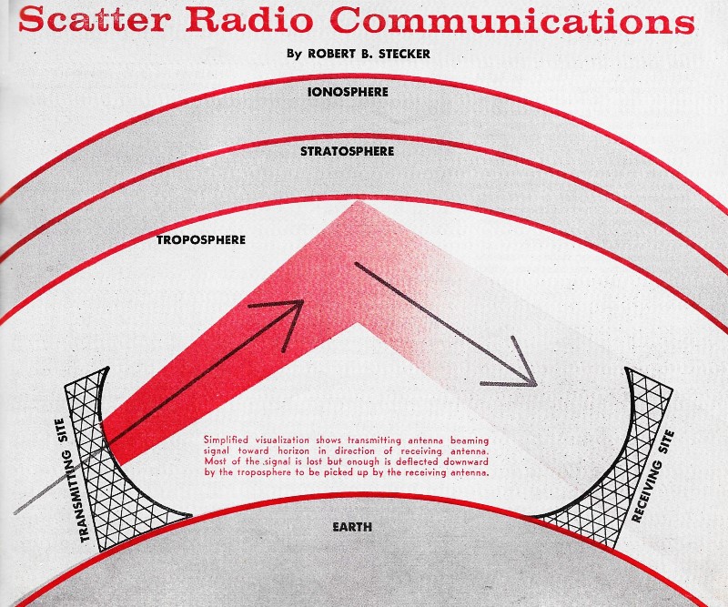
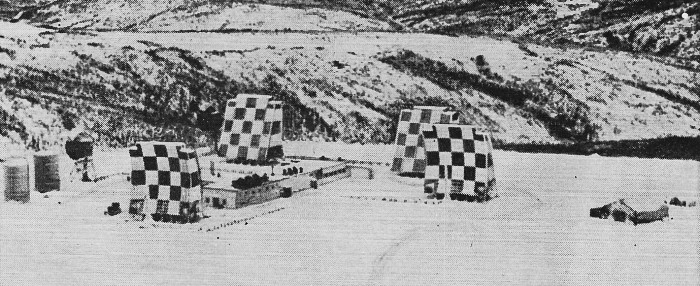
Air view showing four red and white checkerboard scatter communications antennas at isolated "White Alice" station situated on a mountain in northern Alaska. The Transmission Mechanism The troposphere is the layer of atmosphere nearest the earth. It is the area in which almost all weather phenomena takes place. The atmosphere in this six-mile layer acts as a refractive medium to radio frequencies and makes tropospheric scatter transmission systems possible. Tropospheric scatter is essentially a "brute force" type of radio system. Large amounts of radio-frequency energy must be generated. Even with very large antennas to focus the energy toward the distant receiver, almost all of the radiated energy is lost in the troposphere and only a very small portion actually reaches the receiver. The transmission mechanism can perhaps be most easily understood by imagining yourself driving along a dark country road at night. You are approaching a large city which lies just beyond the next hill. As you climb the hill, you can see the glow from the lights of the city even though the lights themselves are below the horizon and out of sight. Although light waves travel in straight lines, a portion of the light has been scattered by dust and other particles in the air and reaches your eye. The scattered light is a very small fraction of the total and so, too, the radio energy which is scattered in the troposphere and reaches the receiver is a minute part of the total energy which has been radiated. Field of Applications This new type of radio system has three distinctive characteristics which tend to define its field of application: 1. Long Repeater Spacing. Depending on such factors as terrain, transmitter output power, and antenna size, high quality tropospheric scatter radio links can span distances ranging from under one hundred to several hundred miles. A typical link with 10-kilowatt transmitters and 60-foot diameter parabolic antennas is about 150 miles long. This offers great advantages over microwave systems, particularly in rugged, inaccessible terrain, where both construction and maintenance costs for strings of intermediate repeater stations, spaced 20 or 30 miles apart, might be prohibitive. 2. High Channel Capacity. High quality tropospheric scatter systems have been built to carryover 100 voice channels. New systems now under construction will have an ultimate capacity of 240 channels. While this is below the capacity of some microwave routes, it far exceeds the channel-carrying capabilities of either h.f. or v.h.f. radio systems. It has proved suitable for all but the heaviest military routes and finds commercial application in thinly populated areas. 3. Freedom from Atmospheric Interference. Properly engineered tropospheric scatter radio systems can provide very high quality and continuous 24-hour reliability since, like microwave systems, they are virtually free from interference caused by such things as ionospheric disturbances, magnetic storms, sunspots, and aurora. This is in contrast to h.f. and v.h.f. systems where service is frequently degraded or disrupted by this type of interference.
Installation men walking by large scatter dish during one of Alaska's fogs. Two other factors combine to make it almost certain that tropospheric scatter systems will be useful primarily in remote areas or for crossing natural barriers, such as lakes or bays. These are the large size of the stations and the high level or radiated radio-frequency energy required. Almost all of the tropospheric scatter systems now in existence use either 30-foot or 60-foot diameter antennas. A few 45-foot size have been used and the introduction of huge 120-foot antennas on some very long links has just begun. A relay station having a pair of 60-foot antennas facing each direction requires in the neighborhood of 10 acres of ground and would be out of the question for urban area installations. Transmitter outputs of 1 and 10 kilowatts have been widely used. Some 2-kilowatt units are also in the field and new 50-kilowatt units are being developed. These power levels are high potential sources of interference in built-up areas. Also, for proper operation and to protect against possible danger from radiation, it is necessary to clear areas immediately in front of the antennas of all structures, trees, and other obstructions, and restrict personnel access in these areas. Mountain-top or seacoast site locations are preferable where the radio beam can shoot into space or out over the water. How Tropospheric Scatter Began The key factor in radio transmission is noise. For successful operation, the signal reaching the receiver must be significantly greater than all the other atmospheric and man-made impulses which appear as noise at the receiver input. Tropospheric scatter systems make use of high power transmitters and very large antennas to deliver usable signals over radio paths with propagation losses in excess of 200 db. By way of comparison, this is some 70 db or 10 million times more loss than that of a typical line-of-sight microwave path. Even with allowable path losses of 200 db or more, the classic "smooth earth" theory of radio propagation would have limited path lengths to under 100 miles. It has long been recognized that some radio energy is bent around the curvature of the earth, but the theory predicted that this would diminish almost immediately to unusable proportions as the distance beyond the horizon was increased even slightly.
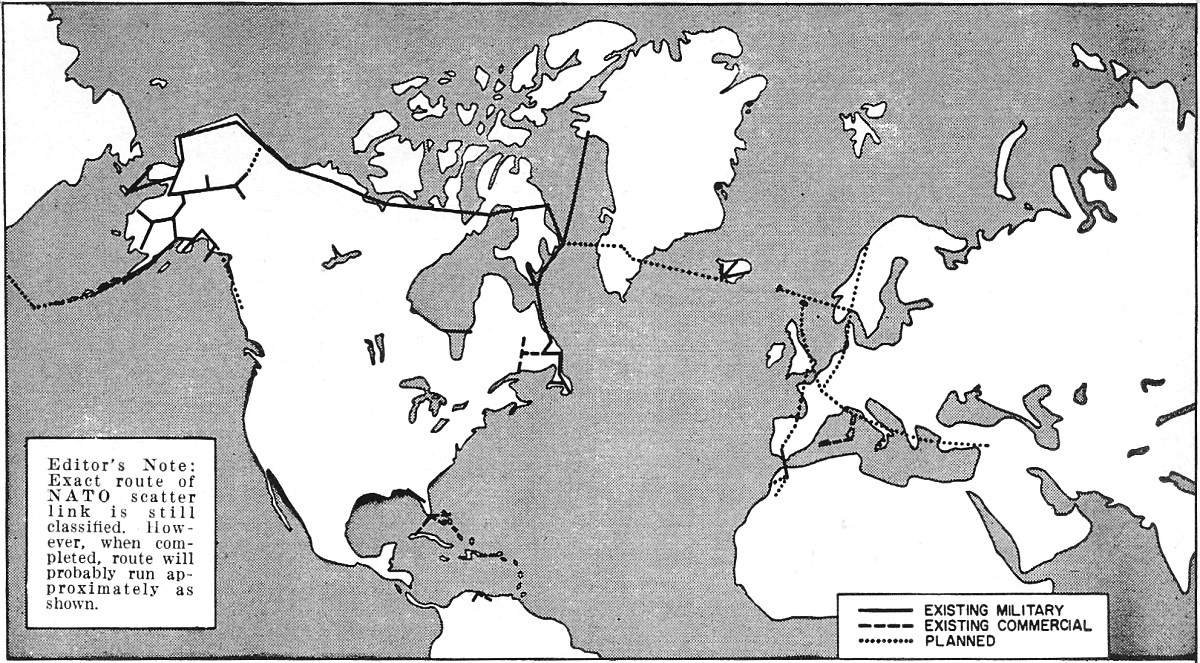
World map showing routes followed by presently existing and planned tropospheric scatter communications links. Both military and commercial systems are indicated. Evidence that this extremely rapid signal attenuation with distance was not being encountered in practice became apparent during World War II. Cases were noted where radar equipment picked up targets at distances theoretically well beyond their maximum range. In the years following the war more evidence was accumulated. The television "freeze" in 1949 was brought about largely because of the unexpectedly high interference between TV stations operating on the same channel although located many miles apart. In the same period the Bell Telephone System was constructing multi-link microwave systems for the transmission of telephone and television channels throughout the country. Here, too, there was concern with "overreach" of a signal from one transmitter into receivers several links down the line and, theoretically, well out of range. A number of studies of this unusual propagation phenomenon were made. In 1950 Kenneth Bulling of the Bell Laboratories summarized information showing that beyond-the-horizon transmission was possible to a far greater extent than had been predicted earlier and suggested that this type propagation be put to practical use in areas where terrain or other conditions made long spacings between repeaters imperative. The first experimental tropospheric scatter system to be built was an 8-link system for the United States Air Force. This system, called by the code name "Pole Vault," provided communication between early warning radar stations in Newfoundland and was completed in 1954. It worked as predicted and proved conclusively that tropospheric scatter radio was a useful new communications tool.
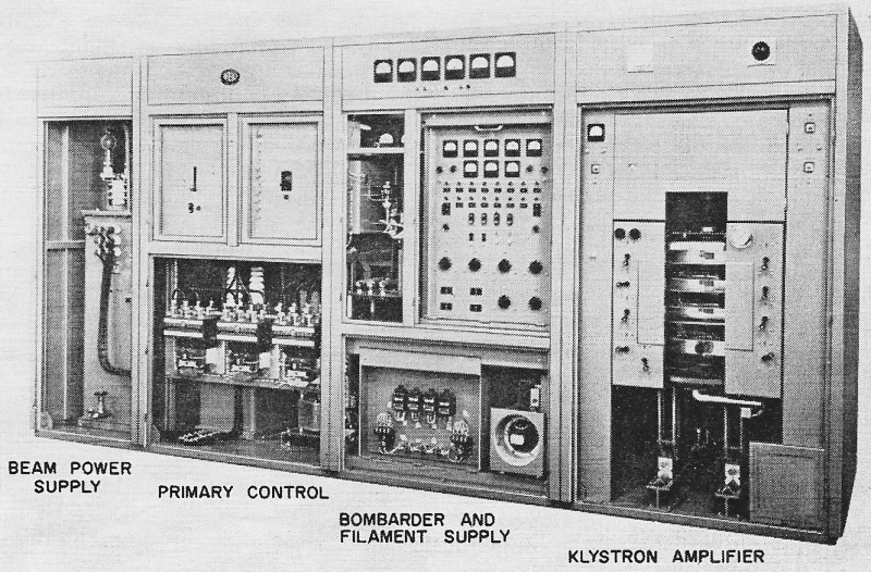
Receiver for scatter communications link employs standard relay-rack construction. Equipment A whole new family of equipment units has grown up to meet the needs of tropospheric scatter. Frequency modulation predominates although some single sideband is used. The optimum frequency band for use with practical antenna sizes is about 750 to 1000 megacycles and most of the systems in the field operate in this range. Good results can also be obtained in the 400-mc. range and the 2000-mc. range has been used although over-all link losses are greater. The velocity-modulated klystron tube has been the means of providing kilowatts of radio-frequency energy at these u.h.f. frequencies. A typical 10-kw. klystron amplifier occupies four 7-foot-high cabinets, one for the klystron itself and three for the related power supplies. It requires less than 10 watts of driving power and about 38 kilowatts of prime power. Water cooling is required and separate heat-exchanger units are furnished for each amplifier. The 10-watt exciter units each occupy one 7-foot bay. They use fairly straightforward frequency multiplying techniques to convert the baseband output of the channelizing equipment into the u.h.f. range. Special modulator circuitry is required when large numbers of channels and very broad bandwidths are used. Superheterodyne receivers with very sensitive low-noise input circuits are used. Like the exciters, each receiver occupies one 7-foot bay. Noise figures of 7-8 db have been obtained using special close-spaced triodes in the first stages. New equipment now being produced will achieve the heretofore impossibly low noise figure of about 2 db by means of parametric r.f. amplifiers. As would be expected when using scatter type transmission, the received signal level tends to fluctuate rapidly over quite a large amplitude range. All tropospheric scatter systems employ diversity reception to minimize the effect of these fluctuations. The early systems used dual space diversity and almost all of the more recent systems use a combination of space and polarization, or frequency, diversity. In such quadruple diversity systems the same signal is sent over four essentially independent paths and received on four separate receivers simultaneously. A combiner circuit takes the four receiver outputs and delivers a single combined output signal to the channelizing equipment. Rigid 3 1/8-inch diameter coaxial cable is used for the high-power transmission lines in the buildings and waveguide - about the size of home heating ducts to handle the relatively low u.h.f. frequencies - is used in the outside runs to the antennas. Some outside runs have used flexible coaxial cables such as "Styroflex" or "Heliax" instead of waveguides when power levels of 1 or 2 kw. were used or when the run was intended for receiving only.
Front panel view of the power-amplifier portion of one of the transmitters employed in the scatter system. A 10-kilowatt klystron amplifier delivers the r.f. output to the antenna. Exciter for this amplifier is in a single, adjacent rack.
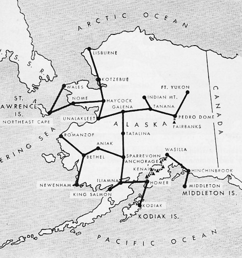
Basic route of "White Alice." Solid dots show scatter stations; triangles and the broken lines show connecting microwave links. Practical System Problems Some of the more serious problems encountered in the construction of tropospheric scatter systems result from the rugged remote areas in which most of these systems have been built. High wind velocities and ice formation have been common and have required strong, heavy antenna structures with massive foundations. Most of the antennas are made of steel. Where severe icing is expected, the antenna structures have been closed in with sheeting to prevent a buildup of ice on the structural members. Some of the enclosed antennas are equipped with large oil heaters for de-icing purposes. The size and weight of the antennas make orientation adjustments a problem. A 60-foot antenna may weigh 100 tons and once emplaced cannot readily be moved to aim it more accurately. This has required that the survey work of establishing precise antenna locations and azimuths, together with the pouring of concrete foundations and erection of the antennas themselves, must all be done with extreme care. A final emplaced orientation accuracy of less than 5 minutes of arc has not been uncommon. Some slight adjustment of the position of the horn feeding the antenna is possible and this permits a slight shifting of the antenna beam by means of defocusing or squinting. Good prime power quality and reliability have been difficult to achieve. Local power generation has been the rule and many of the diesel plants have had inadequate regulation to eliminate voltage and frequency surges as various loads, such as pumps and motors, come on and off. To provide really high communications reliability, the prime power source must be arranged so that continuity of power will not be interrupted by failure of an engine or power bus. The newer tropospheric scatter systems use quadruple diversity, with each station employing two transmitters and four receivers for each link. These form two paralleling transmission paths even when a bus or an engine fails. Further reliability is built into the power plants by using several engines in parallel to feed a power bus instead of a single larger machine. Costs Tropospheric scatter stations have proven to be very expensive. In a large measure this is true because they are so often remote and must be equipped to be self-contained outposts of civilization, complete with power generating stations, sewage and water supply systems, and immense fuel storage facilities. A typical remote repeater station might cost as much as $3- or $4-million. Of this, the radio equipment would account for about $1/2-million and the big antennas about $1-million. Most of the remainder would be spent for construction work of building the site including its access roads and possibly an airstrip. However, even with these high costs tropospheric scatter is frequently more economical than microwave in remote areas. By spanning obstacles such as mountain ranges, rivers and icy tundra wastes in a single bound, it often costs far less than cable or wire systems which require construction and maintenance along every foot of the route and even microwave systems with relay stations every 20 or 30 miles. Existing and Planned Systems In addition to the DEW Line and "White Alice" systems, there are many military networks not as extensive in size. Many new routes are under construction, one of which is the new system being built for NATO, expected to extend all the way from Norway to Turkey.
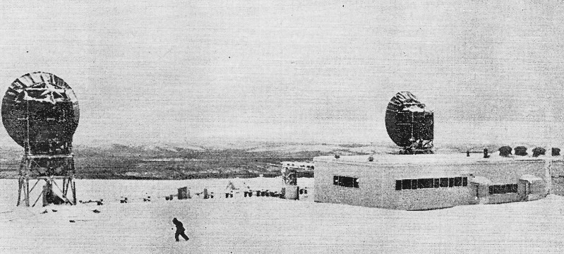
Mountain-top terminal station of "White Alice," northwest of Fairbanks, Alaska. Two dish-shaped antennas are pointed toward the next relay station, 75 miles away. Several commercial tropospheric scatter systems have also been built. A fairly extensive one was recently completed by the Bell Telephone Company of Canada in Quebec and Labrador. Other commercial systems are in the planning stages throughout the world. The only tropospheric scatter system now capable of transmitting television signals is the single link system between Florida and Cuba built jointly by the American Telephone & Telegraph Company and the International Telephone & Telegraph Company. New techniques, together with improved equipment, promise to further extend the usefulness of this new medium. At this time it seems doubtful if the formidable technical obstacles standing in the way of long distance television transmission by tropospheric scatter can be overcome. However, significant increases in bandwidth are being made and the remarkable past history of electronic marvels clearly shows the risk of forecasts which narrowly limit the horizon of the future. One curious result of today's swift scientific pace is that a breakthrough, once accomplished, is accepted as commonplace almost immediately and the race is on to the next obstacle. Inventions which would have been the marvel of other times create little more than a ripple in the stream of today's public consciousness. Electronic engineers and scientists are looking forward to revolutionary changes in the art of communications in the next five or ten years. In much the same way that rocketry and space vehicles have suddenly emerged from the realm of science fiction to become casually accepted realities, communication by such exotic means as underground radio or reflection of signals off space satellites are thought to be much closer to fact than fancy. Cover Story
The antenna pictured is one of many among the 33 stations of "White Alice." When transmitting, many telephone and telegraph channels are combined into a single radio signal which is brought to the feed horn on a tower in front of the huge antenna. The feed horn directs the radio signal against the curved surface of the antenna, which beams the energy toward the horizon and a similar receiving antenna which may be 200 miles away. The aim is precise. The antennas cannot be off as much as 1/20 of a degree. During construction they had to be carefully positioned because once up, these massive structures cannot be re-aligned. The versatility and practicality of tropospheric scatter communication techniques have now been demonstrated for several years by the "White Alice" network with its 170,000 telephone circuit miles and 50,000 telegraph circuit miles. Built at a cost of about $140,000,000, the network paved the way for the new systems now under construction in other parts of the world. Large as it is, the "White Alice" antenna on the cover will be dwarfed by some now under construction. The checkered patterns which mark such antennas as obstacles for fliers will be even more appropriate as the new giants rise into being.
Posted June 18, 2018 |
|
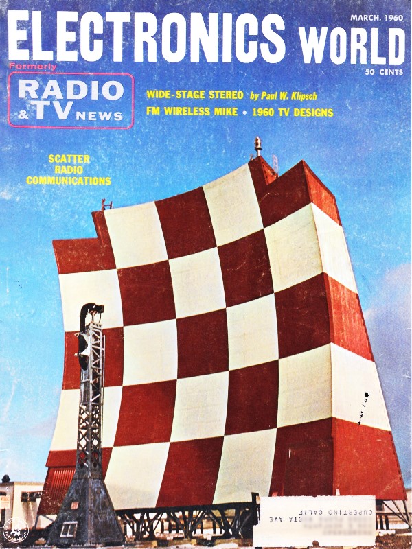


 The checkered antenna, 60 feet tall and made of 100
tons of steel, belongs to Alaska's 3000-mile communications system called "White Alice."
When completed in 1958, "White Alice" was the largest tropospheric scatter network ever
to be built and the first to provide commercial service. The most distant points on the
long-haul system in Alaska include Cape Lisburne, on the northwest tip of North America;
St. Lawrence Island, in the Bering Sea; and Wales, only 56 miles from the coast of Russia.
Some 375 companies and over 3500 persons, under the direction of the Western Electric
Company, manufacturing and supply unit of the Bell Telephone System, in three years built
the network that not only conquered Alaska's lonely distances, but also the static-choked
atmosphere and the savage storms which have always hampered radio and wire communications
near the top of the world.
The checkered antenna, 60 feet tall and made of 100
tons of steel, belongs to Alaska's 3000-mile communications system called "White Alice."
When completed in 1958, "White Alice" was the largest tropospheric scatter network ever
to be built and the first to provide commercial service. The most distant points on the
long-haul system in Alaska include Cape Lisburne, on the northwest tip of North America;
St. Lawrence Island, in the Bering Sea; and Wales, only 56 miles from the coast of Russia.
Some 375 companies and over 3500 persons, under the direction of the Western Electric
Company, manufacturing and supply unit of the Bell Telephone System, in three years built
the network that not only conquered Alaska's lonely distances, but also the static-choked
atmosphere and the savage storms which have always hampered radio and wire communications
near the top of the world.