Readouts and Counter Tubes
|
|
This is my HP5212A Electronic Counter with a unique style of numeric display. Numeric and to a lesser extent alphabetic displays were complicated and therefore expensive prior to the introduction of LEDs. Display component designers went to a lot of trouble to provide users with easily recognizable characters that did not require difficult interpretation to understand. No matter how competent you get at reading a binary number display, quickly understanding a number large than about 32 (5 bits) requires a display consisting of Arabic numerals (or whatever your usual numeral style is). For some reason I can read Roman numbers up to 4999 almost as easily as Arabic numbers, which is most handy for determining copyright years; e.g., 2018 is MMXVIII. But, I digress. Nixie tubes, which have a stack of shaped wires around which when energized a neon or other gas glows, are still very popular for building retro-type equipment. Pixie tubes are fundamentally different in that they have numerical characters punched like a stencil in a metal plate, behind which a gas glows when energized. Both types are available on Amazon and eBay. Readouts and Counter Tubes
Northwestern Television and Electronics Institute Important adjuncts for all electronic counting circuits: indicators that give visual tallies. Editor's Note: In earlier articles, the author has explored the various types of electronic counting circuits and the ways in which they work rather extensively. Now he turns to the matter of usefully extracting information they develop. Obviously indicators that make this information readily available are needed. There are many such, as the author shows. It is characteristic of binary and decade counting circuits that some of the tubes in them are below cut-off while others are at saturation. Which of the tubes are in each of these conditions at any given instant is determined by the number of pulses that have been applied to the input of the counter. Conversely, conditions of the tubes in the counter may be used to determine the number of pulses applied.
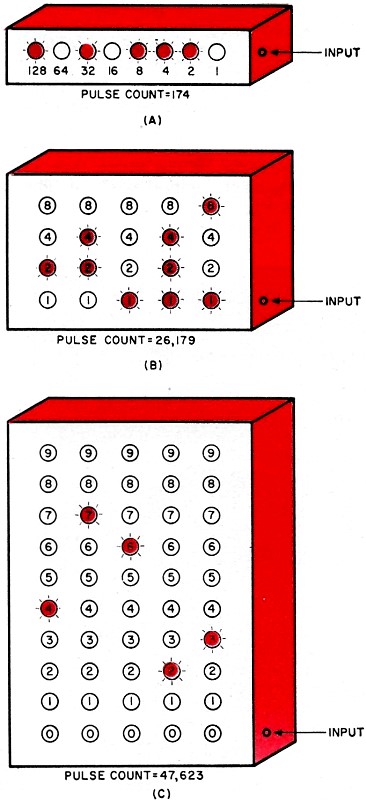
Fig. 1 - Neon readout lamps for (A) pure binary counter, (B) for five 4·lamp decades, and (C) for five 10·lamp decades. Earlier articles have shown how neon lamps may be wired into counting circuits to provide external indication of internal conditions. In fact, neon lamps are frequently used as front-panel indicators on counters. Some typical arrangements of such readout: lamps are shown in Fig. 1. For a pure binary counter, lamps are numbered, from input stage, 1, 2, 4, 8, 16, and so on up, with the total pulse count being obtained by adding the numbers of the lamps that are on. In the pure binary counter of Fig. 1A, 174 pulses have been applied to the input (128 + 32 + 8 + 4 + 2). When a number of 4-lamp decade counters is connected in cascade, the neon lamps are arranged as shown in Fig. 1B, with each vertical column of lamps representing another decade. Here, each of the five decades is assumed to be of the type consisting of four binary stages, with feedback networks being used to re-set each decade on every tenth pulse. The lamps lit in each decade add up to the digit for that vertical column. The right-hand column or decade represents ones or units (8 + 1 = 9, in this case), the next decade represents tens (4 + 2 + 1 = 7 tens, or 70), the next hundreds, and so on. Thus the lights in Fig. 1B indicate 26,179. In Fig. 1C, five 10-lamp decades have been connected in cascade. Again the pulse count is determined by reading the "on" lights, but the task is made easy because only one light at a time must be read in any vertical decade. Nevertheless, there is still a reading problem: except when the digits in all decades happen to be the same, the numbered lights do not appear in a single, horizontal line. For easier readability, several types of in-line readout devices have been developed. The front panel of an instrument using such a device is shown in Fig. 3. It is a digital voltmeter made by Electro Instruments, Inc. In-line readout devices fall into three general categories: 1. The projection type, in which a light source is used to project an image of the desired numeral onto a ground-glass screen. In a variation of this type, lighted-line segments, instead of complete numerals, are selected and projected in such a pattern that they form the desired numeral. 2. The edge-lighted type, in which the numerals are engraved on individual sheets of Lucite. The Lucite sheets for a set of numerals are then stacked one in front of the other. A numeral is then selected for displaying by edge-lighting the sheet on which it is engraved. 3. Multi-element electron tubes with built-in numerals that are made to light up selectively by tube action. These include Burrouqhs Nixie® and Pixie indicators. The general techniques for activating projection and edge-lit readout devices are not too different from those used with neon indicators. Tubes, however, are another matter. Pixie & Nixie Indicators
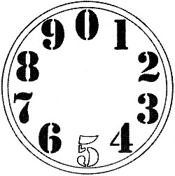
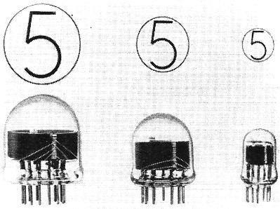
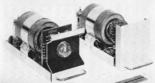
Fig. 2 - One of 10 cathodes in Pixie glows through perforation in the anode. The Pixie readout indicator is a gas-filled tube containing ten cold cathodes located beneath a single disc-shaped anode. As shown in Fig. 2, the anode disc has ten perforations shaped like the numerals from 0 to 9. The cathodes are arranged so that one falls under each perforation. When sufficient voltage to ionize the gas is applied between the disc anode and one of the cathodes, the resulting ionization glow is visible through the corresponding numerical perforation. In Fig. 2, the cathode under number 5 is activated. Numerals can be illuminated in succession as the voltage applied is shifted from cathode to cathode. The Nixie is also a gas-filled tube containing ten cold cathodes and a common anode. In this case, however, the cathodes themselves are shaped like the numerals from 0 to 9. When sufficient voltage is applied between the anode and one of the cathodes, the ionization glow surrounding the selected, numeral-shaped cathode provides visual readout. To accommodate different applications, Nixie indicators are available in a variety of sizes ranging from the miniature to jumbos that provide readable indications 150 feet away. Three sizes are shown in Fig. 4. The numeral 5 above each indicates the relative size of indications, which are viewed looking down at the tubes when they are in the positions shown. Fig. 5 shows two complete, compact, decade counters. The one on the left includes an integral Nixie indicator, with the latter horizontally mounted to provide easy, head-on reading. A number of these compact decades can be connected in cascade and mounted so that their Nixies provide in-line readout. The counter at the right is a similar unit that is used to control a remotely located Nixie. The Glow-Transfer Tube
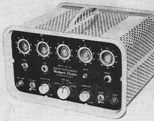
Fig. 3 - An application of in-line readout: a digital voltmeter that provides quick, direct readings. One type of multi-electrode tube has been designed so that it can be operated as a complete, self-indicating decade counter, with no external readout device required. Like other indicator tubes, it is gas-filled, has ten cold cathodes. and a single anode. However it also has other elements to make the counting function possible, which will be discussed shortly, and the cathodes are pin-like structures arranged in a circle around the disc-shaped anode. When ionization occurs between the anode and one of the cathodes, the glow appears as a bright, visible spot at the tip of the cathode pin. As input pulses are applied to the tube, ionization transfers around the circle from cathode to cathode, with the position of the glow thus providing an indication of the pulse count. A counter, made by Westport Electric, using glow-transfer tubes is shown in Fig. 7. The ten cathode positions for each tube have been numbered externally, so that the position of the glow can be read as a decimal digit on each tube. After ten input pulses have been applied to a glow-transfer tube, the glow returns to the initial cathode and the tube produces an output pulse, as do other decade counters. This output may then be used to trigger another tube of the same type to indicate the next decimal position. The counter of Fig. 7 uses five glow-transfer tubes in cascade. It therefore has a total counting capacity of 105 or 100,000. Concerning the tube itself, for each cathode there are two additional electrodes, called guide pins (see Fig. 8). The cathodes are labeled K0 through K9. Between any two adjacent cathodes, there is a pair of guide pins (G1 and G2 for each pair). The latter serve to transfer the glow from one cathode to the next. All of the guide pins identified as G1 are tied together internally and brought out to a single pin on the base of the tube. All G2 guide pins are similarly tied together internally and brought out to a single connection on the tube base.
Fig. 4 - These 3 Nixie sizes. from left to right are super, standard, and miniature. Digits at top show relative size of indications. seen looking down at tubes.
Fig. 5 - (Lower left) Burroughs decade counters including Nixies, like one at left, mount side-by-side for in-line readout. Decade at right controls remotely located Nixie. When voltage is applied to the glow-transfer tube, ionization occurs between the anode and one of the cathodes. There is an external anode resistor, shown in Fig. 6, across which a voltage drop occurs when the tube has started to conduct between anyone cathode and the common anode. This drop immediately lowers voltage across the tube so that it falls below the firing point. Thus a glow cannot form at any cathode except the one that has already been ionized, and only one cathode at a time can be activated. In order to transfer the ionization glow from one cathode to the next adjacent one, we must apply two negative pulses to the tube, one to the G1 pins and the other to. the G2 pins. Furthermore, as shown in Fig. 6, these pulses must overlap in time, so that all G1 pins become negative before the G2 pins do, but that the G2 pins remain negative for a short time after the G1 pulse is completed. These requirements would seem to complicate practical application of the glow-transfer tube, but the matter can be resolved simply: a single pulse source may be used, with a delay network feeding to the G2 circuit. When any particular cathode in this tube is glowing, this is because it is the most negative electrode in its group of elements. Let us assume that this is cathode K0 in Fig. 8. When the first pulse is applied, the G1 pins become more negative than the cathodes. Thus the glow at K0 transfers to the nearest G1 guide pin, which happens to be the one to the right of it, going clockwise. When the G1 pulse ends, the G2 guide pins are the most negative electrodes in the tube, so the glow darts clockwise again to the nearest G2 pin. However, the G2 pulse passes quickly and the cathodes, which are maintained at the lowest fixed potential applied to the tube, become the most negative electrodes. Thus ionization glow transfers to the closest cathode, which is K1 in this example. The fixed potential at the cathode, in the absence of input pulses, is kept more negative than that on other electrodes by the application of a small positive bias to all guide pins from the "B+" line, as shown in Fig. 6. Although each cathode has its own resistor in Fig. 6, a common resistor may be used for all cathodes except K0 in certain applications. Individual resistors, however, permit greater flexibility in using the tube as a ring counter, for an output pulse may be taken from any one of the stages (cathodes) within the tube for external use. When the tube is used only to count by tens, the common resistor is sufficient. In fact, some glow-transfer tubes are designed so that all cathodes except K0 are tied together internally and brought out to a single base pin. This simplifies circuit wiring.
Fig. 6 - This decade counter is built around a single glow-transfer tube. Reset switch forces Xt to X, positive. returning the glow only to cathode Ko.
Fig. 7 - Device with 5 glow-transfer tubes can count to 100,000. Position of glow in each tube can be read by external digits marked on the panel.
Fig. 8 - The anode of a glow-transfer tube is ringed by ten cold cathodes.
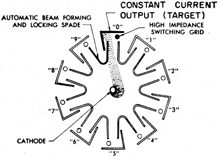
Fig. 9 - MBS counter tube has one cathode. A glance at Fig. 6 shows that, when the normally closed re-set switch is opened momentarily, a positive potential is applied to cathodes K1 through K9 inclusive. At this moment, the K0 cathode is the most negative electrode in the tube, and the glow will occur only at that point. The same end can be achieved by using a negative re-set pulse or voltage and applying it to the independent K0 cathode. Whichever method is used, a definite starting position is provided from which the counting can begin. Once counting has begun, the application of every tenth pulse will return the glow, in its clockwise progression, to the K0 position. The drop that then occurs across the separate resistor of this cathode may then be used as an external output pulse, for application to the next decade in cascade or for other use. In some counting applications where the ratio is less than 10 it is nevertheless desirable to use glow-transfer tubes. The tube is made to produce a lower counting ratio by the method known as forced re-setting. Actually, this technique is related to the use of feedback, described in earlier articles, for reducing the ratio of other counting circuits. For such applications, of course, there must be separate external connections for the cathodes; a tube with nine of its ten cathodes tied together internally is limited to decade counting only. The Beam-Switching Tube The last device to be considered here is one that functions like the glow-transfer tube in many ways, from the practical viewpoint, but is quite unlike it in important respects. The magnetron beam-switching (or MBS) tube has a single, centrally located cathode that is surrounded by ten anodes also known as targets; it thus reverses a relationship already discussed in the glow-transfer tube. Another important difference arises from the fact that the MBS tube is a vacuum type. This permits higher switching rates than can be achieved with gas-filled devices, with some MBS versions capable of switching at rates in excess of five megacycles. Important to the operation of this tube is a cylindrical magnet attached to the glass envelope. The magnetic field produced by this structure interacts with the fields existing between electrodes inside the tube in such a way that it can influence the direction of electron flow. This beaming or deflection technique will be familiar to anyone who knows that magnetic fields, such as those produced by external yokes and focus coils, control the deflection of the electron beam in a TV picture tube. In general terms, operation of the MBS tube may be described as follows: As a result of interaction of the various fields involved, electrons flow from the common cathode to one of the anodes. Each time an input pulse is applied, this flow from the cathode is transferred to the next target. The electron stream thus revolves like the spoke of a wheel, remaining in each of the ten positions used until the next input pulse is applied. After ten input pulses, the electron stream is back to the initial anode target, and an output pulse, as is usual for such decade counters, is produced at that point. A more complete understanding of this action is possible with the help of Fig. 9. This shows that two other electrodes are associated with each target. The one identified as the spade is used to "lock" the electron stream in its path to one anode until the next input pulse is applied. The other electrode, known as the switching grid, is used to transfer the electron stream to the next target. The not unexpected sequence from 0 to 9 identifies the individual targets in the sequence. Although it is not shown in Fig. 9, all even-numbered switching grids are tied together internally, reducing the number of base pins required and simplifying circuit wiring. For the same reasons, the odd-numbered switching grids are also connected internally. Alternate triggering of the odd and even grids will deflect the electron stream so that it transfers from target to target in sequence. A circuit designed around the MBS tube is shown in Fig. 11. The tube itself appears in Fig. 10. In the circuit shown, a binary stage is used to trigger the switching grids. The back-and-forth action of two triodes in the binary provides the alternate switching required. Cathode-follower coupling is used to reduce the loading effect on the binary circuit.
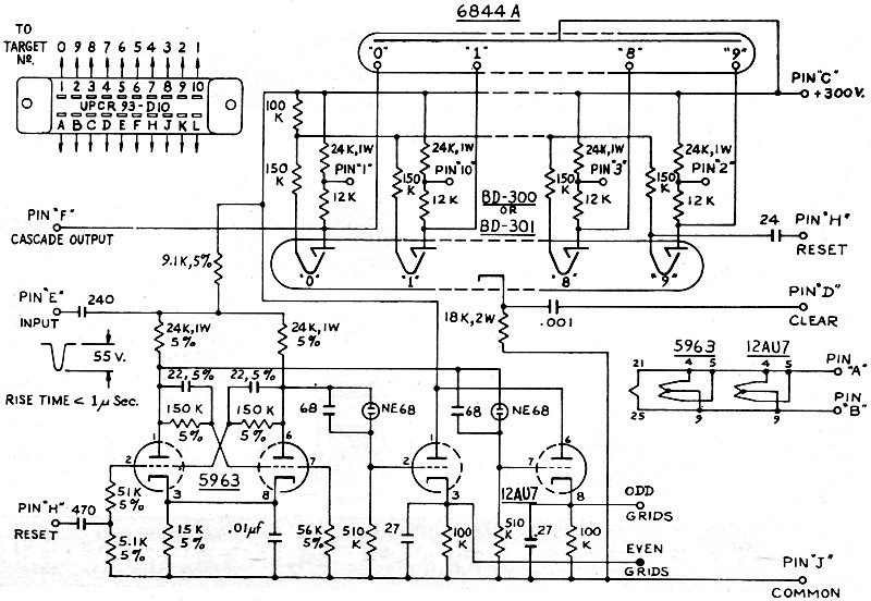
Fig. 10 - Outer magnet rings MBS tube. As ever, there must be some way of clearing the tube and re-setting to the 0 target. In the technique used, a positive pulse applied to the common cathode cuts off the electron stream altogether, thus providing clearing. The pulse is applied at the point marked "pin D, clear" in Fig. 11. A negative pulse is simultaneously applied to the circuit, feeding to spade 9 at the point marked "pin H, re-set." This causes the beam to form in the 9 position, where it is ready to be transferred to the initial or 0 position. A check of the circuit will show that the negative re-set pulse is also applied to the binary stage used for switching. Action of the binary then advances the beam to position 0, the desired starting point. The MBS tube is identified as a type BD300 or BD301. A 5963 is used as the binary. The two sections of the 12AU7 act as the cathode followers, one for each side of the binary. For simplicity, only some of the targets with their associated electrodes appear in Fig. 11. Target 1 shows the types of circuit connections for all odd-numbered anodes; target 8 shows as much for even-numbered anodes; while targets 0 and 9 show the special connections required for clearing and re-setting the circuit to zero.
Fig. 11 - Burroughs DC·106A. Labels for odd and even grids should be reversed. Another, important item in the schematic has not been mentioned. This tube, the 6844A, is a Nixie indicator. Obviously then, the MBS and the glow-transfer tubes differ in another important respect: the former is not self-indicating. However, where the greater counting speed it makes possible is desired, one factor balances out another. It would obviously be impossible to cover every circuit and every type of indication used in electronic counting. However, the reader of this and preceding articles in this series has had the opportunity to become familiar with circuits and special components that cover the vast majority of actual applications. A forthcoming article will cover counting and coding systems actually used.
Posted July 16, 2018 |
|

 By Ed Bukstein