Radio Aids to Aircraft Navigation - Part 3
|
|
This is the third installment on "Radio Aids to Aircraft Navigation," written by Francis Gicca for Electronics World magazine. The first two appeared in the July (LF Ranges and Direction Finding) and August (VHF Omnidirectional Range - VOR) issues. "Terminal Instrument Navigation (ILS & GCA)" covered here in the September issue, are by far the most technical and complicated systems. The Instrument Landing System (ILS) is a "blind landing" system where the pilot navigates the aircraft (airplane or helicopter) along a set of very narrow RF beams configured to provide glide slope and azimuth courses. Ground Controlled Approach (GCA) involves human guidance via radio communications using ground-based radar equipment. I worked on both Airport Surveillance Radar (ASR) and Precision Approach Radar (PAR) very similar to those shown in the accompanying photos. Take a look at my USAF Radar Shop page to see what I mean. Part 1: Low-Frequency Ranges & Direction Finding, Part 2: V.H.F. Omnidirectional Range (VOR), Part 3: Terminal Instrument Navigation (ILS & GCA) You might also be interested in "Omnirange = Air-Safety" in the February 1951 issue of Radio-Electronics, and "Air Traffic Control by Electronics," in the January 1960 issue Electronics World. Radio Aids to Aircraft Navigation - Terminal Instrument Navigation (ILS & GCA)
Senior Engineer, Raytheon Co. Part 3 - Description of two widely used electronic systems that will allow a pilot to perform a safe instrument landing. In the previous articles of this series we discussed the three systems of long-range aircraft navigation which allow a pilot to guide his airplane between distant cities. These three systems: radio ranges, direction finding, and VOR, can make long-range navigation almost automatic. As a matter of fact, there are several aircraft auto-pilot systems which operate with ADF or VOR bearings and actually keep a plane on course automatically. However, the most exact enroute navigation is of no avail unless a landing can be successfully completed at the destination. This final article will describe the two widely used systems of terminal navigation which allow a pilot to perform a safe instrument landing.
ILS localizer transmitter shack. The localizer array inside the building is an 8-antenna linear array. Two antennas, which are placed close together in the center, radiate the modulated carrier signal, and the other six loops are placed symmetrically on either side to form the necessary horizontal localizer course. Before an instrument approach and landing can be performed, it is obvious that an airplane must first be guided away from its long-range enroute course and on a course which leads the airplane to the vicinity of the terminal airport. Most low-frequency radio-range stations have been so located that one of the four courses lies directly over the instrument runway of a nearby major airport. An airplane flying along this on-course radial will thus fly right over the airport and can receive terminal navigation signals to perform an instrument landing. Likewise, ADF beacon and VOR stations are located so that airplanes flying along a specified radial will be guided over a major airport. In high density areas where several major air-ports exist it would be impractical to locate long-range navigation stations so that all airports are covered. In this case, each airport maintains its own short-range navigation station designed to guide airplanes to its vicinity. ADF beacons are widely used by airports for this purpose. Such beacons will guide airplanes to the airport area but not necessarily along a radial which lies along the instrument runway, due to wind-drift effects. Since VOR inherently eliminates the wind-drift problem, VOR is also used to navigate airplanes to the instrument runway. Such terminal short-range VOR is known as "TVOR." All short-range navigation aids are designed to guide airplanes within about 25 miles of the airport where terminal navigation can begin.
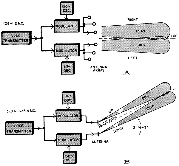
Glide-slope transmitter shack and antenna system. Note the two dipole radiators on pole. These are placed at different heights and are moderately directive horizontally. The lobing of the two antennas in the vertical plane differs because of different heights, and the glide-slope course is formed by the junction of the lower lobe of the lower antenna and the two lower lobes of the upper antenna. The angle of the resultant course is con-trolled by antenna heights. Signals above glide slope have mainly 90-cps modulation, while those below glide slope have mainly 150-cps modulation. A third (modifier) antenna array maintains the glide slope perfectly straight to the touch-down point. Instrument landings should be called instrument approaches since terminal navigation does not actually land an airplane. Rather, terminal navigation allows an aircraft to make a low instrument approach to the end of the runway and, if the runway comes into sight without exceeding specified minimum conditions of ceiling and visibility, a normal landing can be executed. In general, these instrument landing minima are: ceiling 1000 feet, visibility 3 miles. If the weather causes airport conditions to be below these minima then a landing is not legally possible, even with radio aids, and an alternate airport with acceptable weather must be used. Two systems of terminal navigation are in widespread use in the United States today. These are ILS and GCA. ILS allows an instrument approach by reference to cockpit instruments alone. GCA, on the other hand, requires no cockpit instrumentation since all navigation equipment is on the ground. The airplane needs only a functioning v.h.f. transmitter and receiver in order to maintain contact with the GCA controller. ILS The ILS (Instrument Landing System) of terminal navigation was developed during World War II in order to enable properly equipped aircraft to make a safe instrument approach and landing during poor weather conditions without visual reference to the ground. ILS also helps reduce the length of time aircraft must be held aloft during periods of traffic congestion by speeding up instrument approaches. The standard ILS navigation system consists of three separate navigational aids combined to provide a sharply de-fined radio path to the end of the instrument runway. These three aids, the "Localizer," "Glide Slope," and "Marker Beacon," combine to provide lateral and vertical guidance to the runway as well as positive radio fixes along this approach. The transmission and reception of each separate element of the ILS navigational system will be discussed individually and then combined in order to study the over-all operation of this unique system of terminal navigation. The "Localizer" portion of ILS provides a beam course for horizontal, left-right, guidance. It is similar to the low-frequency radio ranges in that it provides a horizontal radio range course oriented along the direction of approach. Fig. 10A shows a simplified block diagram of a typical ILS Localizer transmitter. A 200-watt v.h.f. transmitter operating in the 108-112 mc. band broadcasts the range signal. In the low-frequency radio-range system, position away from the on-course signal is marked by an off-course Morse Code signal which is audibly noted. Obviously, such a system would not be suitable for marking the Localizer course since aircraft position should not depend upon a pilot's ability to hear deviations from on-course when his airplane is so close to the ground. Small deviations from the Localizer course at low altitudes could cause a disaster. The on-course signal, therefore, must be coded in a manner that allows deviations to be electronically detected by an aircraft receiver and displayed on an appropriate cockpit meter.
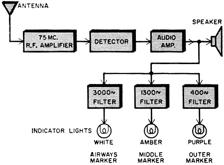
Fig. 9 - Marker-beacon receiver. Fig. 10A shows how the on-course signal is coded. The v.h.f. carrier power is fed to two independent amplitude modulators where the carrier is 20% amplitude modulated by 90- and 150-cycle signals. The modulated Localizer signal is then applied to a broad horizontal antenna array which transmits the Localizer signal. The 150-cycle modulated signal is beamed to the right of the runway centerline while the 90-cycle modulated signal is beamed to the left of the runway centerline. As in the low-frequency radio ranges, these two signals overlap in a narrow beam along the centerline of the runway. Along this beam both signals will be received with equal intensity. To the right of the runway the 150-cycle modulated signal will be stronger while to the left of the runway the 90-cycle modulated signal predominates. Because of the extremely directional characteristics of the v.h.f. antenna array used, the horizontal beam - where both signals are equal in intensity - is extremely narrow. Thus, position from the Localizer centerline can be simply determined by measuring the relative intensity difference between the 90- and 150-cycle signals detected by a v.h.f. receiver. Fig. 11A shows the simple receiver used to detect and display Localizer signals. The v.h.f. receiver is generally the same receiver that is used for v.h.f. communication and reception of VOR signals since these also lie within the 108-127 mc. receiver band. Following detection of the 90- and 150-cycle on-course coding signals by the receiver's audio detector, these signals are separated by tuned filters. The separated signals are then diode detected in order to produce two d.c. voltages proportional to the received strength of the 90- and 150-cycle coding signals. A left-right meter is connected between these two d.c. voltages so that it indicates the difference between them. Thus, if the 90-cycle signal is stronger than the 150-cycle signal, its d.c. volt-age will be larger - which will cause the left-right meter to deflect to the right. This indicates that the airplane is to the left of the runway centerline and a corrective turn to the right should be executed until the meter is centered. The indicator is so sensitive that an angular position error of less than two degrees will deflect the meter off-scale. In most aircraft installations, the left-right meter used for Localizer indications is the same meter used by the VOR converter. The "Glide Slope" portion of ILS provides a second beam for vertical, up-down, guidance. Operation of the Glide Slope is almost identical to that of the Localizer, that is, position from a vertically inclined beam which intersects the end of the runway is determined by measuring the relative amplitude of 90- and 150-cycle coding signals.
Fig. 10 - (A) Localizer and (B) glide-slope transmitters.
Fig. 11 - (A) Localizer and (B) glide-slope receivers.
Fig. 12 - Simplified ILS approach chart for San Francisco's Oakland Airport. Glide Slope transmitters broadcast in the u.h.f. band of 328.6 to 335.4 mc. and radiate a maximum power of 20 watts. Fig. 10B shows a simplified block diagram of a Glide Slope transmitter. As in the Localizer, the u.h.f. Glide Slope carrier is amplitude modulated to about 48% in two modulators by 90- and 150-cycle coding signals. Two simple horizontal dipole antennas mounted on a mast are used to transmit the Glide Slope signal. The upper dipole beams the 90-cycle modulated signal upwards and the lower dipole beams the 150-cycle modulated signal downwards. The beam formed by the overlapping of these two signals is inclined at between 2 1/4 and 3 degrees to the end of the instrument runway and thus forms a vertical glide path that will lead aircraft down to the end of the runway. The actual angle chosen depends upon the nature of the terrain beyond the runway. Fig. 11B shows that the typical Glide Slope receiver is also similar to that used for receiving Localizer signals. However, the Glide Slope receiver is used only for reception of u.h.f. Glide Slope signals whereas the Localizer v.h.f. receiver is also used for communications and VOR navigation. Detected Glide Slope coding signals are separated by two 90- and 150-cycle tuned filters. The signals are then rectified and used to deflect an up-down meter. If the 150-cycle signal is stronger than the 90-cycle signal, the up-down meter will deflect upwards indicating that the aircraft is below the glide path and the pilot must execute a climb until the meter is centered. Since the glide path angle can be as small as 2 1/4 degrees from the horizontal, the Glide Slope indication must be extremely sensitive to small angular position errors since an error of only a couple of degrees could cause a serious crash. For this reason, an angular error of less than half a degree will cause full-scale deflection of the Glide Slope up-down meter. Localizer and Glide Slope indications are often combined in a single cockpit panel meter which may also include a VOR course selector thereby centralizing most navigation functions in a single indicator. The Lear Model 4087 indicator, used in the NAVCOM 100 navigating system, is typical of such a multiple indicator. By following the lateral and vertical guidance provided by the Localizer and Glide Slope transmitters, a pilot can perform an accurate instrument let-down to the end of a runway. However, horizontal and vertical guidance alone is not sufficient for a safe instrument landing for it is vital that a pilot also know his relative position along the approach path. Unless this additional information is provided, it is entirely possible for an airplane to run into the ground at the end of the runway because the pilot did not know he was so close to the ground and could not see the runway. True, the aircraft carries an altimeter, but unfortunately an altimeter is not sufficiently accurate since it is sensitive to barometric pressure weather changes and furthermore tends to lag true altitude during a descent. Therefore, a more accurate, or "positive," fix must be provided. The "Marker Beacon" portion of the ILS system provides this position fix. A "Marker Beacon" is simply a low-powered v.h.f. transmitter whose radiation is sharply beamed upwards to form a flat cone-shaped vertical beam above the station. When an aircraft passes over a Marker Beacon station the signal is received and the pilot then knows he is directly over the station. Thus, appropriately placed Marker Beacons along the approach path indicate an aircraft's position on the path. There are three different types of Marker Beacons. All operate on a frequency of 75 mc. and all radiate about two watts of power. The first type of beacon, known as an Airways Marker Beacon, is used to provide long-range navigation fixes. These airways beacons are located along airlanes and provide positive location on long flights. Airways markers are identifiable because they are amplitude modulated with a 3000-cycle continuous tone and are keyed continuously with 6 dots per second. At some airports, the airways marker is also used as a runway boundary marker and is located about 250 feet from the approach end of the instrument runway. The two remaining types of Marker Beacons are used exclusively for ILS approaches. The "Outer Marker" (OM) Marker Beacon, as its name implies, is located farthest from the runway and generally serves to mark the point at which a descent should begin. Outer Markers are amplitude modulated with a 400-cycle continuous tone and keyed continuously with 2 dashes per second. The Outer Marker is located between 4 and 7 miles from the end of the runway. The "Middle Marker" (MM) Marker Beacon generally marks the point at which descent should cease if the runway is not in sight. Middle Markers are amplitude modulated with a 1300-cycle continuous tone and keyed continuously with alternating dots and dashes. Middle Markers are located about 3500 feet from the end of the runway. A Marker Beacon receiver may consist of a 75-mc. r.f. amplifier and audio detector feeding a cockpit loudspeaker, or it may incorporate circuitry which automatically separates the identifying modulations and indicates type of beacon on a cockpit indicator. Most Marker Beacon receivers used by light aircraft rely upon the pilot to audibly identify the Marker Beacon Morse Code identification. That is, if the pilot hears a succession of dots and dashes from his loudspeaker, he knows he is passing over a middle marker. If, instead, he hears a series of dashes he is over an outer marker, or an airways marker if he hears a series of dots. Fig. 9 shows a type of Marker Beacon receiver which automatically indicates the type of Marker Beacon. A 75 mc. r.f. amplifier, detector, and audio amplifier extract the coding information from the Marker Beacon signal. Three filters tuned to 400, 1300 and 3000 cycles separate the coding signals and apply them to three colored indicator lights. A blue (sometimes purple) light is connected to the output of the 400-cycle filter and flashes when passing over an outer marker. An amber light flashes when 1300 cycles is present indicating the middle marker, and a white light flashes when passing over a 3000-cycle coded airways or boundary marker.
Traffic controllers at GCA radar scopes. Scopes at right are for the Airport Surveillance Radar (ASR), while those at left are for the Precision Approach Radar (PAR).
Fig. 13 - Instrument Landing System (ILS) standard characteristics and terminology. (After a drawing originally prepared by the Air Transport Association of America, and later revised by the Civil Aeronautics Administration.) Most middle and many outer Marker Beacon transmitter sites also transmit a low-frequency "compass locator" signal. This consists of a 25-watt non-directional signal in the 200 to 415 kc. low-frequency band. The compass locator provides a signal for direction finders aboard the aircraft and thus furnishes a means for determining the heading of the aircraft with respect to the desired approach course. In congested areas, low-frequency Marker Beacons are also used to indicate the point at which descent should be started. A unique ILS indicator is used by Bendix in its complete v.h.f. navigational system. A single 3-inch indicator provides Marker Beacon three-light indication as well as left-right, up-down Localizer and Glide Slope metering. A VOR course selector is also included. Terminal Navigation with ILS Fig. 13 shows a complete ILS installation that can be found at most large airports and summarizes the operation of the complete ILS system. Light airplanes generally do not use the complete ILS system because most small plane owners cannot afford the luxury of a separate Glide Slope receiver. As was previously pointed out, the Localizer signal is generally recovered from a v.h.f. receiver which is also used for communication and VOR navigation. The additional cost of a Localizer converter and simple Marker Beacon receiver is small in comparison to the added cost of an additional u.h.f. Glide Slope receiver and converter. National Aeronautical Company's inexpensive Mark II VOR receiver, described in Part 2, also includes a Localizer converter and aural Marker Beacon receiver thereby allowing simple ILS navigation. The lack of a Glide Slope receiver deprives the light airplane of vertical glide-path guidance so the pilot must accomplish his descent with reference to a Rate of Descent meter. ILS navigation charts specify a recommended rate of descent from a fixed altitude over the Outer Marker for various speed aircraft. In the earlier articles we examined how an aircraft can navigate to the San Francisco area using long-range navigation aids. We shall now examine how an instrument approach and landing can be completed at San Francisco's Oakland International Airport using ILS. Fig. 12 shows a simplified ILS approach chart for Oakland Airport. Notice that this particular ILS approach pattern uses a low-frequency radio beacon, Hayward Beacon at 242 kc., to mark the point at which an ILS descent should begin. Therefore, a pilot's first task is to bring his airplane over Hayward Beacon at the proper altitude and heading before an ILS descent can begin. The simplest procedure is to use an ADF receiver to home-in on the beacon itself. Oakland VOR can also be used since the 93-degree radial from Oakland VOR passes directly over Hayward Beacon. The actual procedure to be followed will depend upon the equipment on board the aircraft and specific instructions from the instrument traffic control operator at Oakland. If an aircraft flies towards Hayward Beacon from the east on a heading of 275 degrees and intercepts the beacon at an altitude of 2600 feet, the plane will intersect the ILS Localizer and Glide Slope signals over the beacon. Note that the Localizer signal, at 109.9 mc., intersects Hayward Beacon at a bearing heading of 275 degrees and that the Glide Slope signal, at 333.8 mc., being directed upwards at an angle of 2 degrees-54 minutes intercepts Hayward Beacon at an altitude of 2600 feet. A compass locator broadcasting at 341 kc. is located at the middle marker to help aircraft in lining up along the proper heading of 275 degrees. Upon passing over Hayward Beacon, the Localizer and Glide Slope signals can be followed down to the runway. The outer marker is located 4.1 miles from the end of the runway and an aircraft should pass over this marker at an altitude of 1320 feet. The middle marker is located 0.6 mile from the end of the runway and an aircraft should pass over this marker at an altitude of 230 feet. If the runway is not in sight when passing over the middle marker, the airplane must pull up from its descent. If the runway is in sight, a normal landing may then be made and the aircraft has successfully completed its flight. If the aircraft does not possess a Glide Slope receiver, then descent must be made with reference to a Rate of Descent meter. The ILS approach chart for Oakland specifies various rates of descent from Hayward Beacon for various aircraft speeds in knots. Note that the rate is based upon true ground speed of the landing aircraft. True ground speed is calculated by correcting true air speed for wind air speed. Thus, the pilot must compute his true ground speed before beginning an ILS descent. GCA GCA (Ground Controlled Approach) represents the only terminal navigation system that does not require any navigational instruments on board the landing aircraft. GCA consists simply of a ground-based radar which is capable of accurately tracking approaching aircraft in azimuth and elevation. A GCA traffic controller on the ground observing a radar display can guide an airplane to an instrument landing by literally "talking" the pilot down along a glide path to the runway. GCA was developed originally for the armed forces during World War II and consisted of several independent radar transmitters. Civil GCA today consists of two radar units. An "Airport Surveillance Radar" (ASR) scans an area about 30 miles from the center of the airport and is used for establishing initial contact with aircraft and guiding them along a proper approach course to within about 5 miles from the end of the runway. A second radar, the "Precision Approach Radar" (PAR), then takes over and guides the aircraft down a glide path to the runway.
Multipurpose ILS and VOR indicator which shows "Up-Down" glide-slope indications, "Left-Right" VOR or localizer indications. Lights at upper left are marker-beacon indicators. VOR course selector shows radial angle in numeral window, and "To-From" indication shows in window at upper right. The Airport Surveillance Radar display consists of a Plan Position Indicator (PPI) type of display which shows azimuthal (left-right) direction of aircraft from the airport. The Precision Approach Radar presents two separate displays. A limited angle PPI (B Scope) display shows azimuthal position along the direction of approach. A Range-Height Indicator (RHI) display shows elevation (up-down) position along this approach path. The photograph of a GCA control center clearly shows the types of displays used. GCA could be used as a primary terminal navigation aid, but it is not. Its high cost in comparison to ILS is certainly one of the reasons why ILS is found at every large airport and GCA is not. Furthermore, pilots prefer ILS because it gives them a reassuring shipboard visual indication of position which GCA cannot provide. As a result, ILS forms the main radio aid to terminal navigation in this country. GCA is mainly used as an aid in emergency situations where either ILS equipment fails or an unequipped airplane is caught in poor weather. During the past three months we have examined the operation of our country's major civil aids to aircraft navigation. These navigational systems are unique in the world and illustrate typical American engineering ingenuity. No other federal government in the world provides a more extensive array of aids to civil aviation than the United States, and this is important. In most other countries, civil aviation is virtually non-existent due to tight federal restrictions. In the United States, however, private aircraft far outnumber commercial airliners. In June 1959, for example, privately registered aircraft accounted for 96.2% of all registered airplanes in comparison to the airlines' 1.8%. This means that radio navigation aids should be simple in principle and inexpensive to receive. All present radio aids are just that. As the airlines adopt higher speed jet transports, present navigational aids may not be adequate and longer range aids will be needed. The future will see the development of many new radio aids that will simplify the staggering job of air traffic control and ease air navigation for every pilot, private or commercial. It is certain that these radio aids will strengthen our country's unique belief in the freedom of the airplanes. In closing, the author would like to thank the Federal Aviation Agency, Collins Radio Company, Aero Signal Labs, the National Aeronautical Company, Lear, Incorporated, and the Bendix Aviation Corporation for their friendly cooperation and assistance which made these articles possible. Bibliography Terman, F. E.: "Radio Engineer's Handbook," McGraw-Hill Book Company, Inc., New York, 1943 edition. Section 12, pages 872-901. Henney, K: "Radio Engineering Handbook," McGraw-Hill Book Company, Inc., New York 1950 edition. Chapter 21, pages 1068-1158. Bond, D. S.: "Radio Direction Finders," McGraw-Hill Book Company, Inc., New York, 1944. Hall, J. S.: "Radar Aids to Navigation," MIT Radiation Laboratory Series, Vol. 2, 1947. Lyon, T. C.: "Practical Radio Navigation," Aeronautical Services, Inc., Annapolis, 1955. : Air Navigation for Pilots," U. S. Air Force Manual 51-43, Washington, 1952. Editor's Note: Readers of these articles will be interested in a series of long-play records released by Aero-Progress, Inc., 10493 Santa Monica Blvd., Los Angeles 25, Calif. dealing with radio aids to aircraft navigation. The first of these, entitled "On Course, On the Glide Path" (priced at $5.98 direct from the company), describes and illustrates by means of actual in-the-air recordings the use and sounds of the radio aidss covered by Author Gicca. Other records in the series, entitled "Instrument Flight" and "Aircraft Communications," cover an actual instrument flight from take-off to touch-down and illustrates the use of other aircraft radio equipment by actual examples. For further details, we suggest that our readers contact the company at the above address.
Posted September 2, 2021 |
|

 By Francis A. Gicca