Portable Satellite Communications Link
|
|
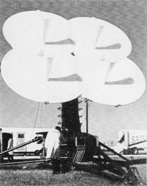
Here you are - portable satellite communications in the mid 1960s per this photo from Electronics World magazine. It has a unique "cloverleaf" ganged parabolic antenna array with phasing control. Today, we have "manpack" type systems which use compact antennas that can be quickly assembled and disassembled in any environment, along with receivers that have sensitivities much greater than the type shown here. Software-defined radio (SDR) technology facilitates programmable modulation and frequency band operation. The Mark V AN/TSC-54 Satellite Communications Link Terminal featured here operated at 8/7.5 GHz up/down. An information page for the Mark V AN/TSC-54 can be found on the GlobalSecurity.org website, which includes in part, "It is completely transportable in two C-130 cargo aircraft." I guess the definition of "portable" has changed a bit since then. Portable Satellite Communications Link
When one thinks of a satellite communications station, what usually comes to mind is a massive parabolic antenna coupled to a large structure housing a formidable complex of electronics. During the past couple of years, however, many companies have succeeded in putting together a highly sophisticated satellite communicator in a very small package. In many cases, these stations are capable of being transported by conventional cargo aircraft to the desired site and then being set up and placed into operation within a few hours by a crew of only half a dozen men. Such a typical station is the Mark V AN/TSC-54 Satellite Communications Link Terminal developed by Radiation Incorporated and shown in the photo. The entire system consists of the antenna portion, which is capable of collapsing down into a small package on its own trailer; an electronics shelter containing all the operating equipment; and a lightweight 45-kW, 400-Hz diesel generator. Total over-all road weight, including crew and sufficient fuel for 72 hours of operation, is 12 tons, which, if desired, can be broken down into discrete 3-ton packages for air transport. Set-up by the six-man crew, time from arrival at the site to actual communications is two hours. The unusual-looking antenna has four 10-foot Cassagrain aluminum reflectors, with the outboard section of each vertical pair of dishes capable of folding laterally on hinges to make the antenna transportable. Each feed emits its energy through a cone-shaped foam dielectric material extending out to a small sub-reflector at the end of the feed. Because of the guiding effect of the foam material, signal losses to the sub-reflector dish are reduced and over-all antenna efficiency is improved. Gain is 52 dB at 8 GHz transmit and 51 dB at 7.25 GHz receive. The antenna is a phase-monopulse type using a special phase shifter which adds and subtracts azimuth and elevation error signals with the sum signal in such a way as to permit the use of conical-scan signal processing in the receiver. These signals are used to drive servo motors which control the tracking movements. The air-conditioned electronics shelter can handle multiplexed voice, Teletype, and facsimile, either directly from on-board equipment or from remote field equipment linked to the terminal by an appropriate communications system. The desired combination of signals is achieved using frequency-division multiplex; this combination is then employed to frequency modulate a 70-MHz carrier, which is passed to the electronic equipment in the antenna pedestal base. The signal is next up-converted to a specific frequency in the 8-GHz band and amplified to 7 kW by a klystron. In the receive mode, the antenna electronics converts the 7.25-GHz input signal to the i.f. and then passes this down to the remainder of the receiver in the electronics shelter. When the equipment is set up and under power, the operator must then locate a satellite. The problem of locking onto a satellite is intensified by the relatively narrow beam width of the antenna (0.3°) and by the fact that the ground terminal's exact location may be unknown. When the operator presses a button, the antenna begins to follow a programmed scan pattern very rapidly. Each satellite is identified by means of a coded beacon signal. If, during the antenna scan, the ground system intercepts a satellite beacon, a relay doses and an integrator (position memory) directs the antenna to the position where the signal was spotted. If the beacon signal is not detected within two minutes, the automatic scan is resumed. If it is detected, automatic tracking begins. The received beacon signature first identifies the particular satellite; then the ground operator selects the appropriate frequencies to be used for that satellite and proceeds to transmit and receive messages.
Posted December 8, 2022 |
|