Mica Capacitors
|
|
Mica capacitors of the leaded, dipped type were used quite a bit in the military electronics assemblies I used to build in the early and middle 1980's while working at Westinghouse Electric Corporation's Oceanic Division in Annapolis, Maryland. They had the characteristic medium brown color and were shiny. According to Arco Electronics author E. M. Rothenstein, mica is one of a very few natural materials directly adaptable for use as a capacitor dielectric. "Mica, being a natural mineral and adapted to use without physical or chemical alteration, is completely inert both dimensionally and electrically. As a dielectric, it will not exhibit aging or deterioration nor subtle variants in electrical properties." In 1965 when this article appeared in Electronics World magazine, mica capacitor tolerances were in the realm of ±0.25%, which is amazingly good, and were useable over the full -55 to +150°C MIL-SPEC range. Values from 1 pF through 1 μF were available. Most likely modern processes have found a way to improve on the natural characteristics. In fact, this 2022 Cornell-Dubilier datasheet for their line of surface mount mica capacitors suggests (IMHO) they are the world's most perfect capacitor. Vintage Arco capacitors can be found on eBay. Mica Capacitors
Mica Capacitor Color Code By E. M. Rothenstein Mica capacitors are widely used because of their high stability and good reliability. This article covers the toil, silvered, reconstituted, molded, and dipped types. Mica is one of a very few natural materials directly adaptable for use as a capacitor dielectric. Its physical and electrical properties, plus its rare characteristic of perfect cleavage, elevate mica to a position of the very best natural capacitor dielectric known today. Its position is further strengthened in comparison with organic synthetics, such as plastic films, and multiple-composition dielectrics, such as ceramics, by reason of its inherent stability. Mica, being a natural mineral and adapted to use without physical or chemical alteration, is completely inert both dimensionally and electrically. As a dielectric, it will not exhibit aging or deterioration nor subtle variants in electrical properties. The property of perfect cleavage enables mica fabricators to split blocks of mica into sheets as thin as 0.0001 inch. The surfaces of the split sheets are parallel, and the splitting along natural crystalline structure lines can be accomplished with relative ease and uniformity. The best of several varieties of mica is muscovite, a particularly clear form with the best electrical performance. It is found primarily in South America and the Orient, with the latter being the principal source. In listing the properties of muscovite mica which pertain to its use as a capacitor dielectric, examination of the figures will provide an immediate explanation of its popularity: Dielectric strength - 3000 to 6000 volts per 0.00 1 inch. Volume resistivity - greater than 2 x 10¹³ ohm centimeters. Dielectric constant - 6.5 to 8.7. Dissipation factor - about 0.0001 at radio frequency to about 0.001 at 60 cycles. Operating temperature - approaching 500°C. Mica, being a natural product, exhibits a non-uniformity of chemical composition and purity. Gross variants are screened out, but variability is still present, as evidenced by the figures just mentioned. Some synthetics have inherently uniform characteristics which will sometimes prove to be a design advantage. Structure
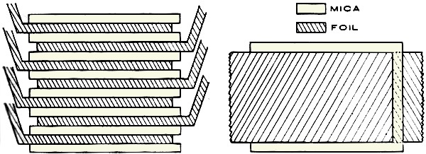
Fig. 1 - Mica capacitors are made in "sandwich" fashion.
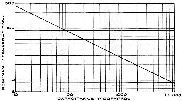
As the frequency of the current passing through the capacitor increases, a self-resonant condition is approached. The capacitive reactance, dominant at normal operating frequencies, decreases, while inherent inductive reactance increases with a rise in frequency. The inductance of the mica capacitor is found in its leads, lead assembly, and the metallic internal structure of the active capacitive section. Actual tests confirm the inverse relationship between resonant frequency and square root of the capacitance value. The inductance of the capacitor remains relatively constant for a given lead length. It is also very nearly the same for all case-size configurations. Shortening the wire leads will effect a modest increase in resonant frequency. As self-resonance is approached, dissipation factor rapidly increases as the resistance of the capacitor becomes a greater percentage of the total impedance. At resonance, capacitor is purely resistive. The use of mica sheets in capacitors is accomplished by the classic technique of interleaving alternate layers of insulating and conducting material, as shown in Fig. 1. Each "sandwich" of insulation between two conductors creates the capacitor, with capacitance being a function of area and spacing of the plates, and dielectric constant of the insulation. Each sandwich of capacitance is paralleled by using tin-lead foil conductors extending alternately from opposite edges of the mica stack. All foils from one side are shorted together and connected to one capacitor termination. The other foils, also interconnected, form the second electrode. Parallel capacitors are additive in capacitance. The conducting foil does not reach to the limits of area of the mica sheet, except on the edge over which the foil extends for electroding. This area between the edge of conductor and insulator is commonly called the "margin." This margin is a safety area to prevent conduction from one plate to another around the edge of the mica insulation. There is danger of a current path through impurities on the surface of the mica or of flashover in air or gaseous material which may exist within the capacitor structure. This is eliminated through provision for adequate areas of non-conducting margin. The earliest mica capacitors in common usage were of a foil structure as described. There were two primary classes, identified as receiving and transmitting. Both these basic styles are still widely used today. The receiving mica is a smaller device for low-power, low-voltage circuits with electrodes clamped to pigtail wire leads. Molded-foil mica capacitors are limited to the order of 0.01 μf., a voltage rating of 2500 v.d.c., and current-carrying capacity measured in milliamperes. The later development of a silvering technique for capacitor plates has expanded these limits. The transmitting mica capacitor, as its name implies, is used in higher power circuits-voltages as high as 30,000 v.a.c. and currents in excess of 100 amperes at radio frequency. To allow mica capacitors to withstand such electrical extremes, it is necessary to increase the mica thickness to gain sufficient resistance to voltage break-down, increase the margin area, pot the capacitor in insulating material to eliminate gaseous elements, reducing the possibility of "flashover" around the edges of the mica and corona, and increase the thickness of the conducting foil to accommodate heavy current. Ribbons of foil are used to connect each plate to the capacitor terminals. When electrical stress levels are too great for the simple parallel capacitor structure illustrated (as in the case of excessive voltage for a single sheet of mica, or an excessive current requirement despite the low dissipation factor of mica as a dielectric material, whose current-carrying capability is limited mainly by the heat generated within the capacitor due to I2R losses), the capacitor sections are connected in series. This provides a voltage-dividing effect, easing the dielectric burden on the individual mica films. Since series connection of capacitors provides a divisive capacitance effect, greater plate area is required per unit of capacitance, and the volume of the capacitor per unit of capacitance is greatly increased. Heat generation within the capacitor is diminished, and the larger surface area of the capacitor enclosure affords faster dissipation of heat to the surrounding environment. For purposes of physical comparison with each other and with other types of capacitors, the molded receiving-type capacitors vary in volume from well under 0.1 cubic inch to somewhat less than a cubic inch. The potted transmitting styles vary from 3 to more than 500 cubic inches in volume. Although some paper and plastic-film dielectric capacitors have made inroads into the mica transmitting field, the latter style of capacitor is still pre-eminent in its area. However, the foil-electrode, molded receiving-type mica capacitor has been largely supplanted by silvered mica capacitors and ceramic dielectric units. The foil mica structure had excellent and unmatched stability by early standards, and there was no suitable substitute for low-capacitance values until the advent of ceramic capacitors. The ceramics eventually replaced foil mica to a large extent in general-purpose, broad-tolerance use where capacitance change with temperature was not a design factor. For the burgeoning market of precise frequency-selective and timing circuits, foil mica did not fill the bill and was superseded by silvered mica and temperature-compensated ceramics. So the original foil mica capacitor today has a very small share of the capacitor market. The silvered mica differs from the foil in that the conductive capacitor plate is a thin layer of silver which is screened and fired onto the surface of the mica. The following advantages are obtained: 1. The exact screening process provides an area on the surface of the mica which is predictable in size and position to a degree not possible in a foil construction. 2. Since the plate is physically bonded to the dielectric, no relative motion occurs in the presence of physical, electrical, or environmental stresses, making the capacitor extremely stable and its variation with temperature closely repeatable. 3. The direct contact of plate and dielectric eliminates the potential presence of air or other foreign matter in the active dielectric area of the capacitor. This preserves the dielectric characteristics of the mica and eliminates instability created by expansion and contraction of air pockets in foil mica capacitors. 4. The obvious instability created by warping or wrinkling of foil during fabrication is eliminated. Slips of conducting foil are still used to provide an electrical path from the silvered plates to the terminals of the capacitor. As in the case of pure foil capacitor construction, the foils are brought out alternately at opposite edges of the stack, folded to the top of the stack, and clinched together with the clamp-lead assembly. Fig. 2 shows a silvered mica capacitor before it is encased in its protective enclosure. In this case, the capacitor is a dip-coated unit. Although mica capacitors are enclosed by means of a wide variety of methods, there are four principal styles. Low-power receiving types are usually molded or dipped; high-power transmitting types are potted in molded plastic cases or in large ceramic tubes with metal terminations. Molded Types The molded-style receiving mica capacitors retained practical exclusivity in the marketplace for some 30 years. The dipped style is a relatively recent innovation. For some time, the mold material was a phenolic resin, and it remains as the case material in a large percentage of molded micas made today. The phenolic resin has excellent electrical properties, good moisture resistance, is hard, and will not flow extensively during molding to contaminate the active capacitance field. However, its high-temperature performance leaves much to be desired, and it is necessary to use an impregnant (usually wax) to obtain a good moisture seal. The phenolic will not bond to the pigtail lead when molding takes place, so a possible moisture path exists at the interface of wire lead and mold material. This must be filled by an impregnant to serve as a moisture barrier. In recent years, softer plastics with greater ease of flow, even at substantially lower molding temperatures and pressures, and better high-temperature characteristics have been used as mold materials. A bond of sorts is made between the material and lead, prompting some manufacturers to eliminate the impregnating process. However, the electrical characteristics of the softer resins are not as good as those of the phenolic, principally affecting dissipation factor, and resin moisture resistance is not as good. Investigation into newly developed plastics for use as enclosure materials continues today, and it is likely that markedly improved mold materials for mica capacitors will appear in the near future. Another facet of molding effects on the capacitor is the tendency toward reduction of the life expectancy and increase in the failure rate of the mica section. The heat and pressure of molding apparently produce a fatigue effect which influences the reliability of the capacitor. This effect is noticeable in phenolic-molded units and manifests itself to a lesser degree in mica capacitors molded in the softer resins. Much higher reliability is obtained in capacitors which have been dip-coated instead of molded. Dipped Types The improvement in reliability, change in lead configuration to increase its adaptability to printed circuitry, reduction of fabrication cost, and some saving in size are all factors in development and rapid industry acceptance of the dipped unit. The reduction in stresses related to en-closure also tends to decrease capacitance change during the finishing process and makes for a more stable capacitor in operation. The dip is usually a combination of resins applied in a series of coats to build up necessary dielectric insulation and a moisture barrier. An excellent bond can be obtained between case material and wire lead, completing the moisture seal. A proper blend of resins will exhibit excellent moisture resistance, electrical properties, and satisfactory performance at a temperature of 150°C. If the dipping is performed at less than atmospheric pressure, a near monolithic structure is obtained, giving the capacitor great strength and physical stability and excluding corona-producing air and other impurities. A minor disadvantage of this technique is the introduction of the case material into the dielectric field of the capacitor. Since the electrical properties of the dip material do not approach those of mica, higher dissipation factor and temperature coefficient is the result. However, the increase in these characteristics is slight, not enough to change the relative merit of the mica capacitor when compared with other dielectric materials. The dipped mica capacitor is still capable of far exceeding minimum published standards in all respects. Incidentally, these published standards are MIL-C-5C for military applications and the Electronic Industries Association Standard RS-153-A. Other Types
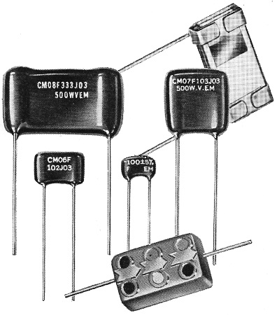
Fig. 2 - An assortment of mica capacitors. Silvered mica capacitor (upper right) is shown before application of coating.
Mica capacitance insulation resistance varies with the environmental temperature present during its operation. The higher power potted transmitting types are enclosed in molded plastic cases specifically designed for the purpose or in large ceramic tubes. The mica capacitor stack is clamped under pressure for retention of physical integrity and minimum spacing between plates. The capacitor is inserted in the case with proper electrical connections made to screw terminals, and the structure is potted. In the case of the large tubular styles, the large metal end caps also serve as terminals, and a compressive force during closure adds to the assembly's strength and rigidity. It might be well to point out that some mica capacitors have been made in tubular forms, using the rolling technique normally associated with paper and plastic-film capacitors. Even the thinnest natural mica sheets are not flexible enough to withstand rolling; but in this case, the rolls of dielectric are not mica in natural form but reconstituted mica. Reconstituted mica is made by flaking the mica into very small pieces and then reorienting the flakes into paper-like thin sheets. usually incorporating a small percentage of organic binder material. The binder material has an appreciable effect on electrical characteristics. However, in one instance, a firing process has enabled re-constitution of the mica flakes into sheets without the use of binders so that most of the basic properties are retained. The use of reconstituted mica capacitors is limited to certain applications for which they are particularly adaptable. Operating Characteristics Whether for receiving or transmitting applications. the principal characteristics of mica manifest themselves in the ultimate decision as to the type of capacitor to be employed. In the case of a high-power application, the decisive factors are the fundamental security inherent in use of this natural material, coupled with electrical excellence when the dictates of application clearly demand mica. A properly designed high-power mica capacitor will operate year after year, withstanding high dielectric stresses and passing heavy a.c. current without noticeable deterioration. During this period, the capacitor may be expected to maintain its original capacitance value within narrow limits, and the effect of changing temperatures is minimal. When we consider low-power applications, again the inherent stability of the dielectric and its relative insensitivity to electrical or environmental variants is decisive. A silvered mica capacitor may be manufactured to extremely close tolerances; but more important, it can be expected to retain the original setting throughout operating life. To verify this fact, it is well to call attention to the fact that when size limitations eliminate the use of air-dielectric capacitors as standards, mica dielectric is used for the fabrication of primary capacitance measurement standards. After establishing the key points of stability and reliability (there is more actual documentation on verified reliability of micas than any other), certain comparisons can be made with other dielectrics. These may demonstrate a narrow superiority of other materials within limited spheres of performance, but for all-around use, mica still plays a most important role. 1. Temperature-compensating ceramic capacitors (specifically NPO zero-temperature coefficient) may have temperature coefficients closely controlled to a point where capacitance variation with temperature may be less than that for a silvered mica capacitor, but the mica will have better long-term aging characteristics, a much lower dissipation factor, less sensitivity to frequency variation, less sensitivity to voltage variation, and smaller size in high-capacitance values. 2. Polystyrene dielectric capacitors may have lower dissipation factor and dielectric absorption, but again, mica will have superior long-term stability, will operate reliably at much higher temperatures, have a much lower temperature coefficient (percentage change in capacitance value per unit change in temperature), and physically be a more rugged dielectric material. 3. Polyester dielectric capacitors may rival mica in reliability (with conservative design), and they may be physically rugged and provide greater capacitance per unit volume. But in all other respects, from a standpoint of electrical and environmental performance, mica remains superior.
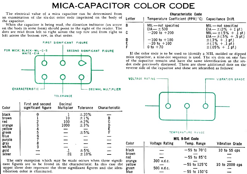
Mica Capacitor Characteristics Mica-Capacitor Color Code The electrical value of a mica capacitor can be determined from an examination of the six-dot color code imprinted on the body of the capacitor. When the capacitor is being read, the direction indicator (an arrow on the body in some form) should point to the right of the reader. The dots are read from left to right across the top row and from right to left across the bottom row, in that order. The only exception which may be made occurs when three significant figures are to be found in the characteristic. In this case the upper three dots represent the three significant figures and the identification color is eliminated. Characteristic Code If the color code is to be used to identify a MIL molded or dipped mica capacitor, a nine-dot sequence is used. The six dots on one face of the capacitor remain and have the same identification as the six-dot code previously discussed. There are three additional dots all the reverse side of the capacitor and these are identified as follows: Mil 9-Dot Code IMAGE HERE
Posted September 19, 2022 |
|