Measurement of Meter Resistance
|
|
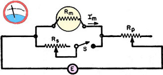
Not many of us are still using multimeters with analog movements for the display. The convenience and fool-proof-ness of digital multimeters (DMM) makes them the obvious choice for the majority of people. In fact, the vast majority of my voltage, current, and resistance measurements are made with a DMM. I still have a couple analog meters which I bought decades ago when first entering the field of electricity and electronics. The crudest type of indicator I have is on my early 1970's vintage Square D Wigginton Model 5008 Voltage Tester with a solenoid indicator. This "Measurement of Meter Resistance" article in a 1960 issue of Electronics World magazine was needed sagacity at the time because the internal resistance (impedance) of the meter and the analog indicator movement might be sufficiently low enough to load down the circuit being measured to the point where an erroneous measurement is made. The presence of a parallel resistance causes the circuit under test to appear as a lower resistance so the voltage divider formed by the source feeding the circuit and the load is skewed. Measurement of Meter Resistance Fig. 1 - Circuit employed to measure the resistance of a meter. See the text above for a complete explanation. By John Gerstle Simple method gives a high degree of accuracy. Does not require elaborate laboratory equipment. It is common practice to measure meter resistance using the circuit of Fig. 1, where Rm = the meter resistance; Rs = a variable shunt resistance; Im = the current through the meter; Rp = the variable resistance to limit the current through the unshunted meter to full-scale value; and E = the voltage source. Using this method, the procedure is to vary Rp until the meter reads full-scale value. The shunting resistor, Rs is then inserted and varied until the meter reads half-scale value. The value of Rs at half-scale is then measured to give the meter resistance. This method is entirely suitable for the well-equipped laboratory where the Rs value for the half-scale reading can be accurately measured on a precision instrument, such as a bridge. For the ordinary experimenter or service technician to whom such laboratory equipment is not available, the following method can be used with a high degree of accuracy. The circuit for making this measurement is exactly the same as that shown in Fig. 1 except that the meter can be shunted with any accurate fixed resistor of a value somewhere near that of the meter resistance. Such a resistor is much more likely to be available or obtainable than an accurate bridge. Actually, it is unnecessary for the shunted meter to be set initially to full-scale value but doing this will give a more accurate result. The equation for meter resistance in terms of shunt resistance Rs unshunted meter current Im, shunted meter current Is, and meter resistance Rm is: Rm = Rs (Im/Is - 1) This equation can be used to calculate the meter resistance even though the shunt resistance is not equal to the meter resistance. As an example, suppose it is desired to measure the resistance of a 1 ma. meter that is known to have a resistance of approximately 30 ohms and, say, only a 25-ohm shunt resistance is available. If measurement shows the shunted meter current to be 0.45 ma. when the 25-ohm resistor is used, then: Rs = 25 ohms; Im = 1 ma.; and Is = 0.45 ma. Substituting these values into the original equation, we have: Rm = 25 (1/0.45 -1 )= 25 (1.22) or, Rm = 30.5 ohms (the value of meter resistance). If, in this example, the usual method of measuring meter resistance had been followed, then: Rs = 30.5 ohms; Im = 1 ma.; and Is = 0.5 ma. or the current when the meter is shunted. Substituting these values in the original equation, then: Rm = 30.5 (1/0.5 - 1)= 30.5 (1) or, Rm = 30.5 ohms. This shows that either method gives exactly the same result. In measuring meter resistance it is not advisable to use a switch to cut in the shunt resistor as most switches, in time, develop enough resistance to introduce inaccuracy when measuring a low-value meter resistance. The switch shown in Fig. 1 was inserted merely to show that the shunt resistor is not always in the circuit. In selecting the fixed shunt resistor, a preliminary check with common resistors should be made to determine the approximate value of the meter resistance should this value be unknown. For high accuracy, the fixed shunt resistor should reduce the meter reading to between 0.4 and 0.6 of its full-scale value. However. any meter reading will give an approximation of the meter resistance.
Posted December 16, 2022 |
|

