Mechanical Filters
|
|
Mechanical filters of the type described in this 1969 Electronics World article are yet another example of the genius of some people. They are actually a form of electromechanical device in that the applied electrical signals are first converted into mechanical signals, followed by resonant mechanical elements that discriminate according to frequency, and finally a conversion back to an electrical signal is made. It is fundamentally the same principal as a crystal, SAW, or BAW filter, albeit each with distinctly different methods and topologies. Mr. Donovan Southworth, of Collins Radio, presents the basics of mechanical filters in this brief write-up. There is an excellent article on mechanical filters on Wikipedia. Mechanical Filters
The author has experience in all phases of mechanical filter research and development. He joined Collins in 1961 after receiving his BSEE degree from Washington State University. His initial work was in the field of synthesis and fabrication of crystal filter networks. Since 1963 he has participated in studies of higher order vibration modes for extension of the mechanical filter operating frequency range, and in the development of filter design by computer programs. He was project engineer of the mechanical Minifiiter and is currently involved in the design and fabrication of mechanical filter networks. By Donovan A. Southworth / Collins Radio Company Mechanical filters are not new, but new manufacturing techniques and new filter configurations have made them "tops" in sophisticated transceivers. Mechanical filters were conceived and designed to provide a unique combination of high selectivity and stability in a compact package at a low cost. Many of these filters use a disk-wire construction (Fig. 1.) which has become popular in our industry. The disk-wire filter is a mechanically resonant device which receives an electrical signal, converts this signal into mechanical vibrations, rejects unwanted frequencies within the mechanical structure, and then converts the mechanical vibrations back into electrical energy. The filter consists of three basic elements: input and output transducers which convert electrical signals into mechanical vibrations and vice versa; high-"Q" mechanically resonant metal disks; and coupling wires which acoustically transmit energy between the disk resonators. In Fig. 3, if an electrical signal is applied to the input coil, it produces an alternating magnetic field that passes through the magnetostrictive transducer attached to the end disk. The transducer, when magnetically biased and tuned to vibrate at the impressed signal frequency, drives the first disk. The short coupling wires connecting the disks drive the next disk, and so on until the signal reaches the output transducer. The output transducer converts the mechanical vibrations into an induced voltage across the output coil and creates an electrical output. Engineers are busy in Europe and Japan, as well as in the United States, designing mechanical filters and resonators. One popular i.f. filter design utilizes a wire-coupled torsional rod. But much of the engineering activity involves units operating below 50 kHz, where physical configurations other than the disk-wire or rod-wire arrangements are more suitable for production. In this frequency range, filters/resonators utilize a tuning fork or flexure mode bar. The devices commercially available in this range are often single resonator types rather than multiple-coupled resonators. Disk-wire type filters are manufactured in the 60- to 600- kHz frequency range with pass bandwidths ranging from 0.06% to 10% (see Fig. 2). The shape factor (60 dB to 3 dB bandwidth ratio) is typically from 2:1 to 1.5:1 although in certain critical applications where even better selectivity is required, shape factors as low as 1.2:1 are being built. Frequency stability with temperature change can be made equal to the stability of a DT-cut crystal. This is one of the most widely used crystal cuts in the 200- to 500-kHz frequency range. Modern network design techniques have resulted in passband response variation of less than 0.5 dB; and insertion loss values as low as 2 dB can be realized, but a more typical value is 6 dB. Prices start around $7.00 and are related to performance requirements. Some Uses Mechanical filters were originally designed in the U.S. for use in single-sideband radios. They contributed to the success of such radios in the early 1950's and are still being used extensively in single-sideband equipment. The small size and weight of a mechanical filter make it very desirable for use in equipment such as manpack radios. These characteristics, in addition to high reliability, excellent frequency stability with temperature, and good cut-off characteristics, combine to satisfy the stringent requirements of military or commercial aircraft communications and navigation equipment. Generally, mechanical filters should be considered for use anywhere that high performance, small size, and reasonable cost are required.
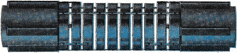
Fig. 1 - Varying the coupling of a multi-element mechanical filter changes its bandwidth. Bandwidths range from 350 Hz - 50 kHz.
Fig. 2 - Available percent bandwidth versus center frequency for a typical filter unit.
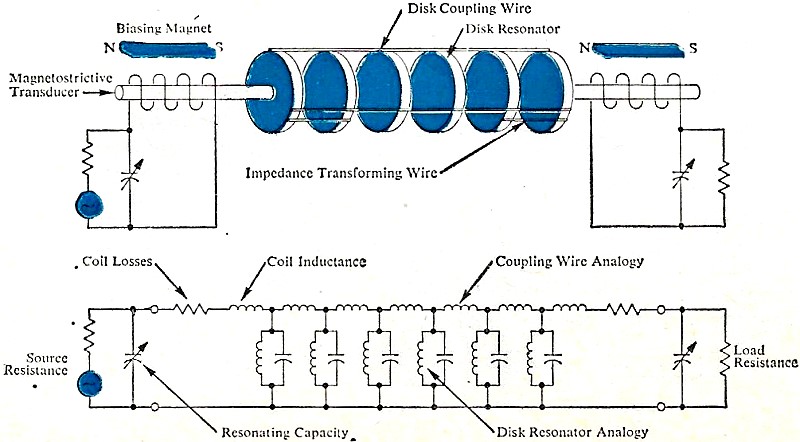
Fig. 3 - An electrical analogy of a typical multi-element mechanical filter. The mechanical vibration of the input transducer is coupled by successive disks to the output magnetostrictive transducer where the vibration is converted into electrical energy. The equivalent circuit is also shown. Mechanical filters made in the U.S. employ two basic transducer types: a nickel-iron alloy wire and a nickel-ferrite rod. The filters which use the nickel-iron wire transducers are essentially self-terminated and have a relatively high insertion loss. They may be driven from any source impedance greater than 50k ohms by parallel tuning the transducer coil, or they may be driven from any impedance lower than 200 ohms by series-tuning the transducer coil. The same conditions apply for the filter output. If the circuit designer finds it to his advantage, a combination of series- and parallel-tuning capacitors may be used. Filters using ferrite transducers have low insertion loss and are designed to work with a specific terminating resistance. For standard filters (either wire or ferrite transducer types), the terminating resistance can be modified using a transformer or capacitor dividing network to match some other value of termination. For special filter designs, the terminating resistance may be specified in the range from 50 to 100,000 ohms. Essentially, the value of resistance determines whether the filter is parallel- or series-tuned. For low-impedance applications, such as conventional transistor circuits, the filter is tuned to series resonance. For high-impedance requirements - FET's, vacuum tubes, etc., parallel tuning is used. All standard mechanical filters are designed with both input and output terminals isolated from ground. This eliminates the need for isolation transformers in applications using balanced loads. However, it is necessary to ground the filter case (either a terminal or mounting studs are provided for the ground connection). In any case, optimum selectivity is achieved when the coupling or "feed-through" between input and output terminals is minimized. If proper care is exercised, 120-dB discrimination is attainable. Picking the Right Filter Some of the characteristics to be considered when specifying a filter are: 1. center frequency or carrier frequency; 2. required passband width; 3. selectivity or skirt cut-off; 4. maximum passband ripple or response variation; 5. maximum insertion loss; 6. source and load impedances; 7. operating temperature range; 8. other environmental requirements, e.g., shock and vibration; 9. package configuration; 10. special requirements, if any, such as particular phase shift or envelope delay requirements. Confusion frequently exists when talking about "passband ripple." Passband ripple is sometimes interpreted to mean the ratio, in dB, between the maximum and minimum amplitude of immediately adjacent peaks and valleys, and does not define amplitudes relative to other peaks and valleys in the passband. A more meaningful interpretation is to use the term "response variation since it always describes the worst-case condition. This term means the ratio in dB between the maximum amplitude and the minimum amplitude occurring anywhere across the entire passband whether these points are adjacent or not. It is important that the equipment designer realize how a particular manufacturer defines this characteristic since it may affect the performance or his equipment. When specifying a filter, the circuit designer should remember that the more stringent his requirements, the higher the cost of the filter. It is usually worthwhile to analyze circuit performance so that the filter will not be "over-specified." Conservative design is always good engineering practice, as long as the designer recognizes that this might increase his costs. The general outlook for the future of mechanical filters is excellent. New filter configurations are being investigated which will result in further advances in the state-of-the-art. For example, lattice configurations, which give the filter designer another degree of freedom, are being utilized. Filters with built-in delay equalization are being realized, resulting in characteristics that heretofore could be achieved only with an expensive filter and a separate expensive equalizer. Piezoelectric ceramic transducers are being used to give another design approach for filters with requirements that were previously unobtainable. Techniques for achieving better selectivity by means of bridged coupling wires have been developed and metallurgical techniques are being expanded to give even better operating temperature characteristics. In addition, advances in manufacturing processes have made it possible to miniaturize and build highly selective filters in less than a 0.07-cubic-inch package. Mechanical filters have far exceeded the original requirements for which they were conceived. Future developments in mechanical filter technology will continue to place emphasis on high quality and sophisticated filter requirements in minimum size and at lowest cost. References Hathaway, J. C. and Babcock, D. F.: "Survey of Mechanical Filters and Their Applications," Proceedings of the IRE, January 1957 Borner, M.: "Progress in Electromechanical Filters;" The Radio and Electronic Engineer, March 1965 Konno M., Kusakabe, C., and Tomikawa, Y.: "Electromechanical Filter Composed of Transversely Vibrating Resonators for Low Frequencies," Jour. of Acoustical Society of America, April 1967 Johnson, R.A. and Teske. R. J.: "A Mechanical Filter Having General Stopband Characteristics," IEEE Transactions on Sonics and Ultrasonics, July 1966.
Posted December 21, 2017 |
|