Mariner Spacecraft: Explorers of Mars
|
|
"Mariner" was the project name given to NASA's first fleet of interplanetary spacecraft, headed for both Venus (1, 2, 5, and 10) and Mars (3, 4, and 6 - 9). When Mariner 4 launched for Mars in 1964, it marked the first time mankind had successfully sent a probe to "the red planet." It radioed back Mars surface images at a resolution of 2 miles across. Fifteen missions later, we now have vehicles roving the Martian landscape drilling holes for soil samples, crunching rocks, sniffing the air and determining chemical compositions of the aforementioned, measuring temperature, wind speed, atmospheric pressure, seismic events, and perhaps most importantly testing for signs of life. Mariner 4's radio subsystem transmitted data back to Earth at 2300 MHz. Depending on where Earth and Mars are in their orbits, it can take anywhere between 4 and 21 minutes for signals to span the ether between them. That means if a command signal is sent from Earth to a Mars craft and a response is immediately signal sent back to Earth, the round-trip time can be between 4 and 42 seconds - a delay even worse than with two cellphones talking to each other on Earth. For comparison, it takes about 1-¼ seconds (1-½ round-trip) to the moon. Mariner Spacecraft: Explorers of Mars By Fred W. Holder Bendix Field Engineering Corp.
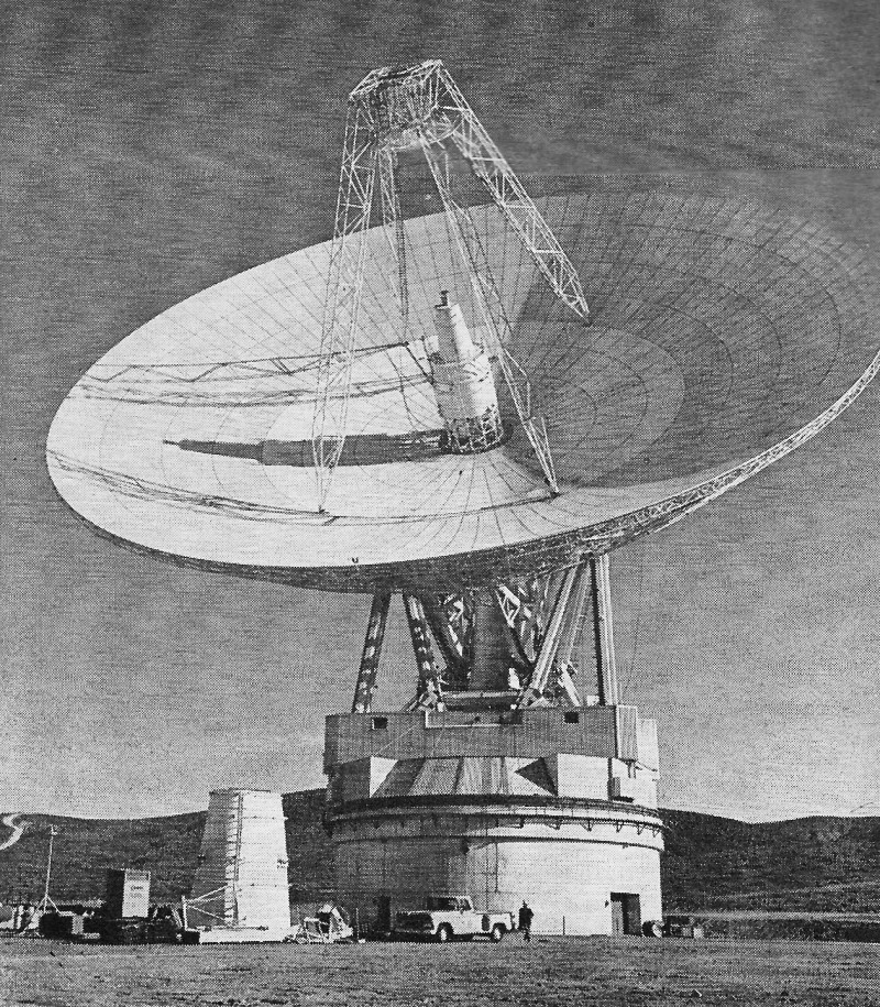
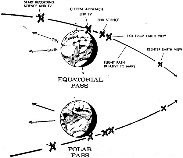
Mariners VI and VII, launched early this year, are adding to our knowledge of the distant red planet to which we may some day travel. Here is what the scientific packages were designed to accomplish. This 210-ft antenna at Goldstone, Calif. is used to communicate with the Mariner spacecraft and other deep-space probes. On November 28, 1964, an Atlas/Agena rocket roared off the pad at Cape Kennedy, Florida. The 575-pound Mariner IV spacecraft was on its way. Its mission: To gather scientific information on the red-orange planet, Mars. Eight months and 325,000,000 miles later Mariner IV was within 6118 miles of the Martian surface. On July 15, 1965, Mariner slewed its TV camera into position and snapped 21 pictures of Mars. A breakthrough had been achieved. The Mariner photographs showed surface features as small as two miles across. Even the most powerful telescopes and the most favorable atmospheric conditions on Earth have never yielded such high-resolution pictures of the Martian surface; their best resolution shows surface features 100 miles across. Early this year, two more Mariner spacecraft (Fig. 1), propelled by the powerful Atlas/Centaur rocket, were hurled into space. Their mission: To fly within 2000 miles of the Martian surface and to further the exploration begun by Mariner IV. These spacecraft, designated Mariners VI and VII, were launched in February and March, one month apart. Mariner VI will journey 226,000,000 miles to take close-up TV pictures of the equatorial region of Mars on July 30, 1969. Mariner VII, on the other hand, will travel a somewhat shorter distance and just five days later, on August 4, 1969, will photograph the polar region of Mars (Fig. 2). Such lengthy journeys through the bitter cold vacuum of space pose several problems which the designers must solve if the spacecraft's passenger, the scientific data package, is to reach its destination. In this article we will investigate some of these problems, see what the scientific package may accomplish, and what NASA's Jet Propulsion Laboratory (JPL) in Pasadena, California has planned for the future. Power Generation The Mariner IV spacecraft needed almost 200 watts of electrical power to operate its functional components over the 1,534,000,000 mile journey, which officially ended on December 20, 1967. This power was furnished by 70 square feet of solar-panel area containing 28,224 solar cells. When Mariner was in the vicinity of the Earth, these panels generated about 700 watts of electrical power. As Mariner approached Mars, the output from the solar panels was reduced to 300 watts, leaving a good margin of power in case of solar-cell damage. The electrical systems of Mariners VI and VII require a maximum of about 388 watts at the time of Mars encounter. The power is supplied by 83 square feet of solar-panel area which contains only 17,472 photovoltaic solar cells. At Earth distances from the Sun, these solar panels produce about 800 watts of power, but as the spacecraft approaches Mars, the power capability decreases to 449 watts, leaving an adequate margin in case of degradation caused by solar flares.
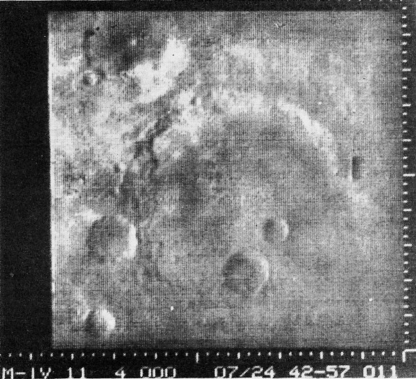
Picture of Martian surface sent to Earth by Mariner IV (1965). Each spacecraft carries a rechargeable, silver-zinc battery that is a sealed unit containing 18 silver-zinc cells. This battery has a minimum capacity of 1200 watt-hours at launch. This capability is reduced to about 900 watt-hours at Mars encounter. Power from the solar cells is directed to the battery to keep it in a state of full charge so that it may be used during Mars encounter as an emergency backup power source. Each spacecraft carries two power regulators to provide a redundancy factor. If one regulator should fail, it is automatically removed from the line and the second regulator is switched in to assume the full load of the spacecraft. Also, should an out-of-tolerance voltage condition exist in the main regulator, the standby regulator takes its place in the line. The primary power distributed to most of the spacecraft systems is a 2400-Hz square wave. However, the gyro spin motors use a 400-Hz three-phase current. The infrared spectrometer and the scanning motor are supplied with a 400-Hz single-phase current. The transmitter amplifier tube, battery charger, and temperature-control heaters use the unregulated d.c. power from the solar panels or from the battery. Temperature Control An object in space will be warmed on the side facing the Sun's rays and cooled by its own radiation into the black sky around it on the side away from the Sun. If the object is not rotating, the sunny side may be several hundred degrees hotter than the shady side. And an object at Earth distances from the Sun may be 125° F warmer than it would be at Mars distance. The Mariner spacecraft and its electronic components couldn't tolerate these adverse conditions. Therefore, it was necessary for the engineers to devise methods of maintaining certain temperature limits within which the electronic components could operate properly. Heating by direct sunlight on the Mariner spacecraft is minimized by the use of a thermal shield of aluminized Teflon on the sunny side. The side away from the Sun is also covered with a thermal shield to prevent rapid loss of heat to the cold of dark space.
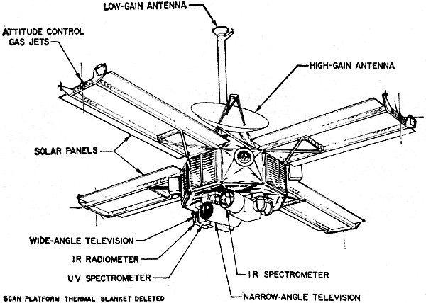
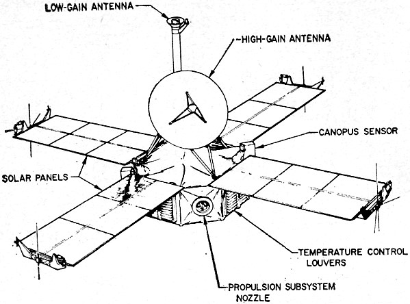
Fig. 1 - Spacecraft used for Mariner VI and VII missions.
Fig. 2 - Trajectories of Mariner spacecraft past Mars. The temperature is controlled in the spacecraft's six electronic compartments by the opening and closing of polished metal louvers that are actuated by coiled bimetal strips. These strips act as spiral-bound springs that expand and contract as they heat and cool. This mechanical action is calibrated to provide an operating range from fully closed at 55° F to fully opened at 90° F. Each pair of louvers operates independently on its own local temperature, as determined by the internal power dissipation within the compartment. Other elements of the spacecraft are temperature controlled by means of paint patterns and polished metal surfaces. For example, the high-gain antenna dish, which is dependent upon the Sun for its surface heat, is painted green to keep it at or near room temperature during planet encounter. At Earth distances from the Sun, the antenna dish is at its upper thermal limits. Communications Broadcasting continuously at 2300 MHz with 10 watts of power, the radio subsystem in Mariner IV provided a communications link over which scientific and equipment performance data was returned to Earth at a rate of 8 1/3 bits per second for most of the flight. As Mariner approached Mars, it took 12 minutes for these radio signals to travel the 134,000,000 miles back to Earth. The signal reaching the big, 8.5-foot antennas on Earth was 10-19 watt, a bit faint for conventional receivers. For example, the average home TV set receives a signal of about 10-7 watt. All communications between the Mariner spacecraft and the Earth is in digital form. Command signals transmitted to the spacecraft are decoded, translated from binary form into electrical impulses, and routed to the proper destination within the spacecraft. Data gathered in the spacecraft is converted to digital form for transmission back to Earth. In Mariner IV, two transmission rates were available: 33 1/3 and 8 1/3 bits per second. Early in the Mariner IV flight, the spacecraft was switched to the 8 1/3 bits-per-second rate. Mariners VI and VII have five different data rates for transmission: the engineering channel has 8 1/3 and 33 1/3 bits per second at any time, the science channel has 66 1/3 bits per second during encounter and 270 bits per second during data storage playback, and a high-rate science channel at 16,200 bits per second. This latter science channel can be used only when the 210-foot antenna at Goldstone, California is available to receive data. Unless Mariners VI and VII are receiving uplink signals, they transmit a frequency of 2195 MHz, which originates within the spacecraft transmitter. The transmitter consists of two redundant exciters and two redundant radio-frequency power amplifiers in any combination. However, only one exciter-amplifier combination will operate at any one time. Both amplifiers on each spacecraft employ traveling-wave tubes. They are capable of operating at 10 watts or 20 watts output and can transmit through either the high-gain or low-gain antenna. The S-band receiver used in Mariners VI and VII operates continuously during the mission at a frequency of about 2115 MHz. The receivers in the two Mariners operate at slightly different frequencies. These receivers are used with the low-gain omnidirectional antenna only and receive the uplink command and ranging signals from the ground stations of the Deep Space Network. Television
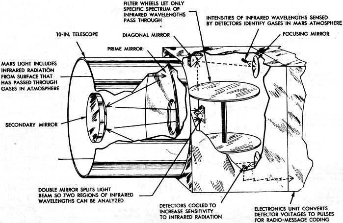
Fig. 3 - Details on the infrared spectrometer that is used to identify gases located in the lower atmosphere of Mars. A brief review of the TV subsystem in the Mariner IV spacecraft provides a basis for comparing the systems used in Mariners VI and VII. In Mariner IV, a 12-inch focal length telescope with a 1-degree field of view brought the image to a vidicon tube having a 0.22-square-inch faceplate. The image was scanned in 200 lines of 200 dots or picture elements each. The TV camera converted the scanning image to a digital signal of 240,000 bits per picture. The digital picture data was recorded on a two-track, 1/4-inch magnetic tape loop 300 feet long which was capable of recording a little more than 21 pictures. Each of the 40,000 elements in a picture was converted to a six-bit binary number (64 possible numbers) representing picture shading from pure white (binary 000000) to jet black (binary 111111). It took more than eight hours to transmit each picture back to Earth at a rate of 8 1/3 bits per second. The bits were transmitted as pulses which were present (1) or absent (0). The binary numbers representing picture elements were fed into the computers at NASA's Space Flight Operations Facility at Jet Propulsion Laboratory. The computers processed the data so it could be fed into a digital photographic processor. In one method used, this processor converted each number to an appropriately shaded dot. The dots were then projected in sequence (200 dots per line for a total of 200 lines per picture) onto a cathode-ray tube. Each completed picture was photographed by a 35-mm camera. Mariners VI and VII each carry two cameras. Camera A is similar to the camera on Mariner IV, except that it has been equipped with a wide-angle lens and covers an area 12 to 15 times larger than the Mariner IV camera. It has approximately the same resolution - two miles. The resolution of camera A is one-tenth that of camera B, and its photographs cover an area 100 times larger on the surface of Mars. The best resolution for camera B is expected to be about 900 feet, compared with two miles for the Mariner IV camera. The vidicon tubes in the TV cameras of Mariners VI and VII operate in a manner similar to that used in Mariner IV, except that the electronic beam scans 665,280 points on the picture image. As in Mariner IV, each point is converted to a shading number and recorded on a digital tape recorder. Each picture will be represented by 3.9 million bits of information. Transmission of the picture data back to Earth is in binary form. Once the information is received at the Space Flight Operations Facility, it is converted to electrical pulses, representative of the pattern of light and dark elements of the original image on the vidicon tube. These pulses will intensify a beam of light as it is swept across a 70-mm negative to expose it at 665,280 points to recreate the original image. The standard approach plan programmed in the on-board computer in each spacecraft provides for 50 approach pictures. Whether or not this plan can be implemented is dependent upon the availability of the 210-foot antenna at Goldstone, which will allow transmission of these pictures to Earth at 16,200 bits per second before the flyby. If the "big dish" is not available, an alternate approach will be used in which eight approach pictures will be taken for transmission to Earth after the flyby. As the spacecraft fly by Mars, they are each scheduled to take a series of 24 close-up pictures of the surface at a closing range of from approximately 6000 to 2000 miles from the surface. Red, green, and blue filters will be used on camera A to delineate color differences, while a yellow filter will be used on camera B to reduce haze. The approach pictures are expected to give scientists the first detailed pictures of features previously studied from Earth. These photographs may serve to locate haze, clouds, or dust storms and allow studies of changes during the time each series is made and during the five-day interval between the two spacecraft. The television pictures may allow scientists to detect any moist areas on the Martian surface. The innermost of Mars two moons, Phobos, might appear in one of the approach series. Other Scientific Experiments
Fig. 4 - Details on the ultraviolet spectrometer that is used to identify the gases located in the upper atmosphere of Mars.
Fig. 5 - Infrared radiometer for surface-temperature measurements. The scientific payload of Mariner IV was made up of six devices besides the television subsystems: (1) a helium magnetometer to measure planetary and interplanetary magnetic fields; (2) a solar plasma probe to measure the quality rate and energy of positive ions "solar wind"; (3) an ionization chamber and Geiger-Mueller tube to measure the ionization caused by charged particles; (4) a trapped-radiation detector to measure the Earth's Van Allan belt and to check for similar formations around Mars; (5) a cosmic-ray telescope to detect protons and alpha particles; and (6) a cosmic-dust detector that is employed in order to measure momentum, direction, and the number of hits from cosmic dust. In addition to the TV subsystem, Mariners VI and VII carry an infrared spectrometer, an ultraviolet spectrometer, and an infrared radiometer to be used to explore the surface and atmosphere of Mars. These devices are designed to yield data on the physical, chemical, and thermal properties of the planet. They will probe the surface and atmosphere of Mars in the visible and near-visible portions of the electromagnetic spectrum, from the infrared region through the visible portion of the ultraviolet region. The S-band occultation experiment, which requires no special equipment other than the spacecraft's radio, will provide new values for atmospheric pressure and density, and electron density in the Martian atmosphere. The infrared spectrometer (Fig. 3) will detect infrared radiation in the 1.9 to 14.3-micron region. It will allow detection of water, carbon dioxide, methane, ethylene, and acetylene, if present. The presence of organic molecules would provide evidence of the existence of either past or present life on Mars. This detection, however, would not be conclusive. The ultraviolet spectrometer (Fig. 4) identifies different species (molecules, atoms, and ions) by the wavelengths of light they absorb or emit. Each species absorbs the energy of light (which is composed of a number of different wavelengths) at one or more wavelengths and re-radiates the absorbed light at the same or longer wavelengths. An atom, for example, re-radiates the wavelength it absorbs. The spectrometer can detect certain wavelengths and thus identify the species. This device uses two photomultiplier tubes as detectors. Each of these tubes is sensitive to different regions of the spectrum. One tube responds to the 1100 to 2150 angstrom region, the other from 1500 to 4350 angstroms. The infrared radiometer (Fig. 5) is boresighted with the television cameras to allow correlation of surface temperatures with terrain features and clouds. This provides a map of the surface, relating temperature variations to surface features. The unit uses two antimony-bismuth, five-junction thermopile detectors to provide 30 readings every 63 seconds. Twenty-seven of these readings will be of planetary temperatures, two of them will be calibration readings, and the remaining reading will be an engineering measurement on the instrument itself. One of the detectors covers the 8 to 12-micron range; the other covers the 18 to 25-micron range. Filters are used to determine the wavelengths actually reaching the detectors. If frozen water exists on Mars, there is a possibility of detecting localized moist areas on the surface. This would require a higher surface temperature in the area, which would be detectable. The experiment may also determine if the bright rim seen on the craters in the Mariner IV photographs of Mars are remnants of carbon dioxide or water ices. Future Missions Two more missions to further explore Mars are in the planning stage. The first of these missions is scheduled for 1971 when two Mariner spacecraft will orbit the planet for three months. The first spacecraft will orbit at an inclination of 60 degrees to the planet's equator. This orbit would permit it to examine about 70 percent of the Martian surface. The second spacecraft would then be placed in the near-polar orbit, inclined 80 degrees to the planet's equator. This orbit will permit examination of the Mars polar caps and provide high-resolution coverage of selected areas. It will also permit oblique views of broad areas of the planet's surface and possibly an examination of the planet's two moons, Phobos and Deimos. In 1973, NASA plans to send two spacecraft to Mars. Designated Project Viking, the two spacecraft will be launched in mid-1973, about ten days apart. Each spacecraft will consist of a Surveyor-type soft-lander mated with a Mariner 1971 class Mars orbiter. The Mars orbiter will provide power and communications support to the landers during the cruise period. Upon arrival at Mars, the orbiter propulsion system will be used to place the orbiters and landers into a Mars orbit. After reconnaissance of potential landing sites by the orbiters, the landers will be detached and will soft-land, using the techniques developed for Surveyor and the Apollo Lunar Module. The orbiters will then provide broad-area surveillance in support of the landers, in the same way that the Lunar Orbiter and Surveyor spacecraft worked as a team in exploring the Moon. The exploration of Mars began 3 1/2 centuries ago when Galileo distinguished the disc of Mars with the first astronomical telescope. Such exploration has continued through the centuries with ever-increasing sophistication, with larger and more powerful telescopes and more sophisticated photographic equipment, to the missions of Mariners IV, VI, and VII. We can only hope that the data provided by the Mariners of 1971 and 1973, as well as those in the present series, will give us an even more comprehensive picture of the red planet.
Posted September 11, 2017 |
|