Glass-Dielectric Capacitors
|
|
Continuing with the series on capacitor types, particularly dielectric material, this July 1965 Electronics World magazine article reports on glass materials used by Corning Glass Works. Glass dielectrics are popular for aerospace and space applications because of their tolerance for high radiation levels found in regions not protected by the Earth's atmosphere. Glass compound consistency provides for mass producing values with tight tolerances and exceptional parameter tracking over temperature. High "Q" values and low loss at extreme temperature and high frequency (at the time) made them the component of choice by missile and satellite designers. 0.5 pF through about 0.01 μF is the typical value range for glass dielectric capacitors. Author Archer Martin mentions radiation exposures of 1018 NVTth, which appears to be a measure of neutron flux exposure, but I could not find a good definition of the term ("NVT," without the "th" is used here). Glass-Dielectric Capacitors
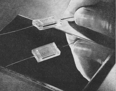
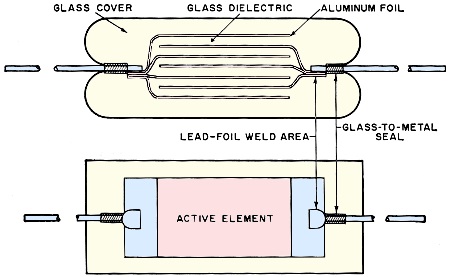
A typical glass capacitor such as those discussed in the text. By Archer N. Martin / Corning Glass Works Known best for its aerospace applications, this capacitor is now being used in other high-quality circuitry. Various types of glass capacitors, with their characteristics, are described. The history of the glass capacitor began in World War II, when the sources of natural mica were threatened. Because glass is electrically and physically stable and chemically inert, the Signal Corps and Bureau of Ships suggested that Corning Glass Works begin development of a glass dielectric to replace capacitor mica. An optical-grade, lead-potash composition was produced with electrical properties equal to and in some cases better than those of mica. A process was then developed to form the glass in an extremely thin ribbon of practical width. With this dielectric, the company introduced a commercial glass capacitor in 1951 that was a direct substitute for the mica capacitor. The capacitors are made by stacking alternate layers of aluminum foil and glass ribbon until the desired capacitance is obtained, then fusing the assembly into a monolithic block as shown in Fig. 1. The same glass composition is used for both the case and dielectric, insuring that the electrical properties of the capacitor are entirely those of the dielectric. Leads are welded to the electrodes to form a glass-to-metal seal where they enter the case, creating a truly hermetic capacitor. Military specification MIL-C-11272 was written to describe only glass capacitors but has been broadened in recent years to include other types.
Fig. 1 - Basic construction of the glass-dielectric capacitor unit.
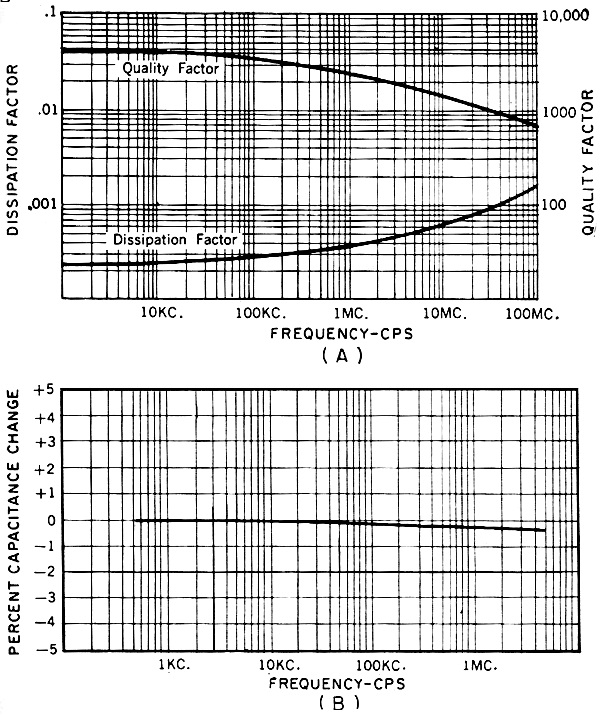
Fig. 2 - (A) Quality and dissipation factor and (B) percent capacitance change with frequency for glass dielectrics.
Fig. 3 - (A) Insulation resistance and (B) capacitance change with frequency for glass-dielectric capacitors.
Plastic-potted glass capacitors are made for printed boards. Because of interest generated by the exotic aura of aerospace missions, the glass capacitor is known mostly for its application in missiles and spacecraft. With the glass capacitor, Corning was the first company to meet the Minuteman component-reliability research and development goals of the Autonetics Division of North American Aviation. This singular success helped make the glass capacitor famous, but it also may have tended to obscure its usefulness in fields aside from the specialized one of reliability. A creditable market exists for the component in such equipment as high-quality test sets, measurement instrumentation and process controls, in such functions as high-"Q" filtering, reliable bypassing in r.f. circuits, and peripheral computer applications, and in other systems where circuit parameters cannot be allowed to wander. The singular advantage of glass-dielectric capacitors is the way they help circuit designers predict the operation of their circuits. There are few components possessing as sturdy and consistent a history of stability and reliability. The manufacturer states, for example, that any two of its units, regardless of capacitance value or size, exhibit temperature coefficients within 10 PPM/°C of each other. For a designer, this means that his circuits containing many capacitors will track accurately and predictably during temperature variations. In addition, retrace of the TC of glass capacitors is essentially absolute, assuring negligible hysteresis. Capacitance drift with load life is less than 0.5%. Voltage coefficient is stated as zero, so capacitance can be expected to remain the same despite voltage levels or surges. Other specs that characterize the glass capacitor are extremely low losses and high "Q", even at elevated temperatures and high frequencies. With such low losses, designers an realize higher "Q" and the resultant narrower bandwidths in filters and tuned circuitry. Characteristics Most glass capacitors range in capacitance from 0.5 to 10,000 pf. (0.01 μf.) but can come as high as 150,000 pf. (0.15 μf.). The capacitance range below 10,000 pf. makes up about 15 to 20% of the total capacitor dollar. Tolerances for glass capacitors range from 1% to 20%, d. c. working voltage is generally between 300 and 500 volts but can be made as high as 6000 volts, and operating temperature range is from -55 to +125°C. Fig, 2A shows the range of quality factor ("Q") and dissipation factor with frequency, while Fig. 2B demonstrates the percent capacitance change with frequency. Fig. 3A shows the insulation resistance with temperature curve for glass capacitors, while Fig. 3B illustrates the capacitance change with temperature. Temperature coefficient (TC) of these capacitors is +140 ±25 PPM/°C at 100 kc. with essentially absolute retrace. At any given temperature, the TC will not deviate from the curve by more than 5 PPM. Load life is less than 0.5 % capacitance change after 2000 hours at 125°C with 150% of rated voltage applied. The change in resistance with moisture is negligible with the hermetically sealed units, and the plastic-potted types show an insulation resistance in excess of 1010 ohms after standard military tests. Radiation resistance, except for the plastic-potted units, shows no significant change in capacitance from exposure to levels of 1018 NVTth. The plastic-potted unit (Type TYO) was developed to provide a glass capacitor at prices comparable to those of ceramic units. Potted in a plastic shell, this device has parallel radial leads spaced symmetrically with the square-cornered case on 0.1-inch grids. This unit lends itself to fast, high-density, upright installation on printed-circuit boards. Two other types of glass capacitors are designated CYFR and CYFM styles by the company. Both are fusion-sealed, thus making them virtually impervious to environment. The CYFR capacitors have an established reliability figure, proven under Minuteman stress conditions, of 99.9996% per thousand hours at a 60% confidence level and at full-rated voltage at 125°C. Stated another way, this figure means that no more than four failures (deviation from specified performance) will occur in a billion part-hours of operation. The CYFM style is electrically and environmentally interchangeable with the CYFR. However, the former units provide cost savings up to 60%, since they do not undergo the expense of extensive reliability testing and documentation. Another type of glass capacitor is represented by medium-power transmitting units, designated CY60 and CY70 rated at 1 kva. and 7.5 kva., respectively. Power ratings significantly higher than listed can be easily obtained merely by making sure that the operating temperature of the capacitor remains below 125°C. This can be done with terminal and/or body heat sinks. Terminal heat sinks are very efficient because of the many layers of solid aluminum that extend into the capacitor. The CY60 and CY70 capacitors are used for r.f. applications such as power amplifiers, low-power transmitters, and many electronic devices in grid, plate, coupling, tank, and bypass functions. Their relatively small size and low weight make them suitable for airborne equipment and mobile transmitter applications. Performance of the glass capacitor is a direct function of its dielectric. The composition is closely controlled by the manufacturer from day to day, month to month, and year to year, and unlike mined dielectrics does not have to be graded or culled. During more than a decade of commercial experience, this control is what has given the glass capacitor its reputation for stability, reliability, and performance predictability.
Posted September 12, 2022 |
|