Electronics in Outer Space
|
|
You might know that America's first communications satellite, Pioneer I, failed to obtain a proper orbit due to component failure. However, according to author Jordan McQuay, "[The] first use of a satellite as a radio relay station occurred accidentally during the one-day flight of Pioneer I in October 1958. The electronics payload included a command receiver, which was supposed to trigger a reverse rocket and thus propel the vehicle further into space. Although the rocket failed to function on command, the command signals were instantaneously rebroadcast by the data transmitter aboard the Pioneer I. These command signals were heard half-way around the world!" That was two years before before Echo I, a reflective sphere designed to be a passive radio relay platform, was put into orbit in 1960. Unfortunately, I do not yet have parts 1 and 2 of this series that appeared in Electronics World. Electronics in Outer Space
By Jordan McQuay Some interesting applications of artificial earth satellites as space communications relay stations as well as for television transmissions. The previous parts of this series have covered some of the specific electronic equipment used in outer space. This, the concluding article, will cover the application of satellites as communications relays and as part of a television transmission system. Communications Relays Although satellites and space probes provide a wealth of scientific and environmental data, specially equipped electronics payloads can provide a number of direct communication services. Chief among these is the use of satellites as space relay stations. First use of a satellite as a radio relay station occurred accidentally during the one-day flight of "Pioneer I" in October 1958. The electronics payload included a command receiver, which was supposed to trigger a reverse rocket and thus propel the vehicle further into space. Although the rocket failed to function on command, the command signals were instantaneously rebroadcast by the data transmitter aboard the "Pioneer I." These command signals were heard half-way around the world! Not so accidental was the "talking" satellite known as "Project Score" - for Signal Communications by Orbital Relay Equipment. Carried aboard an "Atlas" missile and operated successfully during December 1958, this electronics payload had been specifically designed as a radio relay station for operation in the upper atmosphere. This was also the first step toward future "courier" satellites for military types of communication requiring extreme security of operation. The payload consisted essentially of an FM messenger receiver (150 mc.) , a control switching circuit, a commercial-type magnetic tape recorder, an FM message transmitter (132 mc.), and a battery power supply. The payload also included a beacon or tracking transmitter (108 mc.). See Fig. 15.
Fig. 14 - The four paddle wheels on "Explorer VI" carry 8000 solar cells for power. The FM message receiver operated continuously. Other components of the payload were not in operation except when activated by the control circuit. When the appropriate command signal was received from a ground station, the control circuit triggered anyone of three operating conditions: (1) turned on the tape recorder to receive messages from ground stations; (2) turned on the tape recorder to play back, and turned on the FM message transmitter to broadcast the recorded tape; or (3) connected the output of the message receiver directly to the FM message transmitter. With conditions 1 and 2, the electronics payload functioned as a delayed repeater, with no limitation on the time between receipt and rebroadcast of a message. With condition 3, the payload functioned as an instantaneous radio relay. The payload accepted and relayed voice messages and as many as seven teletypewriter channels. It was loaded, switched, and triggered successfully throughout the 12-day period of its existence - proving the feasibility of space relay stations. Other, more sophisticated, payloads are being developed for use during the next two years. These will feature refined circuitry and expanded operating bandwidths up to about 100 kc. By 1965, bandwidths of from 4 to 5 mc. will be achieved, making possible the long-distance relay of television signals by space relay stations aboard orbiting satellites. Photoelectric Systems
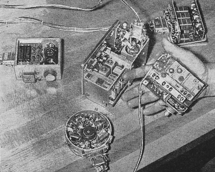
Fig. 15 - The elements that form the electronics payload employed for the Project "Score." Being held at the right is the 10-ounce command receiver. Behind it is the electronics control unit. The large unit in the center is the FM message transmitter, with its power converter at the left. Foreground unit is 3/4-lb. beacon or tracking transmitter. Special types of optical sensory units have been developed primarily for mapping and crude surveillance of large areas. These units employ photocells with appropriate scanning devices and switches. Characteristically, they can distinguish only between light and dark areas; but they can map effectively in terms of black-and-white contrast - such as between sea and land regions. They can be used similarly to record the distribution of clouds over the surface of the earth or other planets, again in terms of black-and-white contrast. But in any application, photoelectric sensory units provide poor definition. First of these optical sensory units was part of the electronics payload aboard the "Pioneer I," but was not operative because the space probe failed to reach the vicinity of the moon. The sensory unit will be used on later space probes for the identical purpose of mapping areas of the moon and other planets. Such a sensory unit consists essentially of a scanning device (Fig. 15) and two photocells and other elements sensitive to infrared illumination. The entire unit is contained in a barrel which turns as the space vehicle rotates in flight. There are two small circular apertures on each side of the barrel. Each aperture is equipped with a small mirror-type telescope and is armed with a hydraulic timer. At an altitude above 100,000 miles, the earth offers too small an image to activate the photocells but when the space vehicle is pointed properly on a pass near the moon or any other planet, the reflected sunlight from the planet is sufficient to enter both apertures and trigger the photocells simultaneously. These signal impulses are broadcast by the data transmitter. By this method, a "strip" of the region is scanned, with the photocells registering impulses for all sunlight reflections. Enough of these "strips," placed alongside each other, provide a crude electronic "picture" of the distant surface - devoid of much definition, but with enough black-and-white contrast to differentiate between water and land masses. Another type of optical sensory unit was used in "Vanguard II" satellite to determine the distribution of clouds around the earth. Essential elements of the unit are two photocells mounted behind circular, gridded windows projecting from opposite sides of the satellite. The photocells project opposite each other at an angle of 45 degrees from the spin axis of the satellite, so that one always sweeps the surface of the earth. After amplification, signal impulses from the photocells are fed directly to a magnetic tape recorder containing a 75-foot erasable tape. The recorder operates only when the photocells are scanning the sunlit part of the earth - about 50 minutes out of every hour. The recorder is turned off during darkness by an automatic switch activated by solar cells. When interrogated by a ground station, the command receiver in the electronics payload triggers the recorder and the data transmitter and an entire 50 minutes of taped data is broadcast in a single 50-second "burst" of data transmission. Then the payload is reset to record again as the satellite continues its orbit around the world. Television Systems
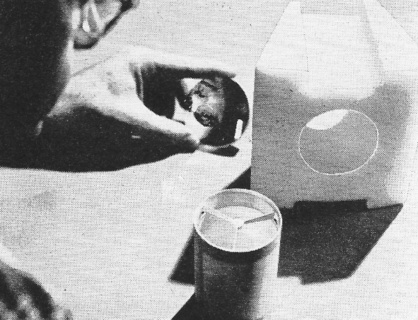
Fig. 16 - Being held in the photograph above is the scanning device for photoelectric cell sensory unit in the "Pioneer I." Refined types of optical-viewing satellites for the future will utilize small TV cameras as the sensory units of their electronics payload. In a very real sense, these are the sophisticated successors of the photocell devices described previously. A TV system is far more desirable because of its higher definition characteristics. Initial satellite to be launched will be in the shape of a shallow cylinder, resembling a "flying saucer" and spinning about ten times per minute at an altitude of from 200 to 500 miles above the earth. Three TV cameras, of the RCA "Vidicon" type, are installed around the periphery of the cylinder. One camera has a field of view of about 1000 miles with a resolution of about 2.5 square miles. The second camera, with a smaller field of view, resolves a square of about 0.5 mile. The third camera, with the smallest field of view, resolves a square of about 0.1 mile or slightly more than 500 feet. The TV camera with the widest field of view is aimed perpendicular to the spin axis of the satellite and the other two are aimed in the same direction but along the spin axis. Each camera produces signal impulses in accordance with the amount of sunlight reflected by the surface of the earth. Cloud areas reflect about 80 per-cent of the sunlight; land about 15 to 20 per-cent; water surfaces about 5 per-cent. Each camera scans for a fraction of a second and stores the data on a magnetic tape during about two seconds. This results in three channels of data, one from each camera. Subsequently. on command from a ground station, the data is broadcast by a 3-channel multiplex data transmitter. The TV sensory units are controlled by an automatic switch activated by solar cells so that the cameras operate only during daylight hours. An electronic cut-off device prevents the cameras from operating when a large percentage of the useful viewing area is outside their field of vision. Although initial uses of TV cameras aboard earth satellites are primarily for meteorological purposes, such space vehicles have tremendous military potential for the direct surveillance of various areas around the world. Ultimate development of larger satellites will make possible larger and more sophisticated electronics payloads, permitting the use of more definitive TV cameras and related equipment for a wide variety of surveillance purposes. Toward this end, at least nine such satellites will be launched during the fall and early winter of 1959, each equipped with a TV-type sensory unit as the principal payload - and each payload weighing about a ton. These satellites are part of the extensive "Project Sentry." Power Supplies
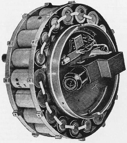
Fig. 17 - Series bank of mercury batteries used as power supply in "Pioneer III." The majority of U. S. and Russian satellites and space probes have utilized mercury or chemical batteries as the principal source of power. Where space and weight are not critical, this is an obvious choice. As future space vehicles accept larger payloads with higher power requirements, mercury or chemical batteries will be utilized more widely. In the early days of space exploration, however, weight and volume were factors of significance. For these reasons, clusters of solar cells were employed to power the data transmitter aboard the "Vanguard I" launched in March 1958. Light energy from the sun incident on each of six clusters of solar cells, connected in parallel, produced about 50 milliwatts - enough to operate the data transmitter. So successful was this conversion process, that today this satellite - still circling the earth - continues to transmit temperature data and will continue to do so for hundreds of years. A further development of the solar-cell power supply was used for "Explorer VI," launched in August, 1959 (Fig. 14). Here, four paddle wheels, each 20" x 20" with 1000 solar cells on each side, generate electricity to recharge internal chemical batteries. With the decided trend to larger space vehicles, however, weight and volume are no longer critical considerations - and chemical or mercury batteries will find continued and expanded use. Operating power for the "Pioneer III" was supplied by a ring of 18 mercury batteries, built into a periphery around the electronics payload (Fig. 17). In "Project Score," a battery of zinc-silver oxide cells provided operating voltages ranging from -6 to -18 volts d.c. - coupled with a d.c.-d.c. converter for obtaining higher voltages. While these cells had a capacity limited to about 1000 watt/hours, they were intentionally selected because of the anticipated short life of the satellite. All of these power sources are severely contrasted with a radically new type: the nuclear battery. Several kinds are under development, of which two - the tritium cell, and the strontium 90 cell - will be used in satellites and space probes during 1960 and 1961. While these tiny batteries yield only a few microwatts of power, they will last an incredibly long period of time - about 20 years. Although it is certainly difficult to predict exactly what will happen to electronics in that period of time, one thing is certain - electronics is going into outer space!
Posted July 11, 2018 |
|
 Part 3