Units and Standards of Electrical Measure
|
|||||||||||||||
In 1988, the National Bureau of Standards (NBS) was re-named National Institute of Standards and Technology (NIST) because a government bureaucrat needed to justify his/her position and the financing to change all the signs, brochures, and letterhead would be paid for with OPM (Other People's Money, pronounced like 'opium'). Regardless of its name, the NBS is charged with establishing, maintaining, and enforcing standard units of measure for the country, as well as with coordinating standard units with other countries. It is interesting to read how standards have changed over the years, and what methods have been suggested for establishing those standards; e.g., the Ohm (Ω) could have been based on a foot of copper wire weighing 100 grains, an English mile of No. 16 copper wire, a kilometer of iron wire 4 mm in diameter, and a column of mercury 100 cm long and 1 mm. in cross-section at 0°C. This 1964 article delves into the historical aspect of some common electrical standards for resistance, capacitance, inductance, voltage, and current. Units and Standards of Electrical Measure
The practical standard for d.c. voltage is provided in this country by saturated standard cells forming National Reference Standards. These cells are extremely stable, but sensitive to change in temperature. Both the reference cells and cells sent to the Bureau for calibration are kept in a circulating oil bath whose temperature is electrically controlled to within a few thousandths of one degree of 28 degrees centigrade. Examination of our National Standards, their derivation, maintenance, and accuracies, and an assessment of the present state of the art. By Forest K. Harris Chief, Absolute Electrical Measurements Section National Bureau of Standards If we wish to say how large some physical quantity is, our description of its size has two parts - a unit and a number. The unit is a defined reference amount of the quantity; and, if our statement is to be understood, everyone who is concerned must agree on the size of the unit. The number, which completes our statement, tells how much bigger or smaller is the quantity we are discussing than the defined unit quantity. The size of the unit can be fixed by definition, quite independently of any measurement, and therefore can be exact. We can arrive at the numerical part of our statement only through measurement-this number is subject to the errors of the measuring process by which we obtain it, and therefore can never be exact. Thus if a statement of quantity is to have meaning, there must first be agreement on the size of the unit. Next, there must be acceptable reference standards to represent the physical embodiment of the defined unit or some multiple of it; and it is through such reference standards that measurement errors are controlled. Reference standards form the basis for the calibration of measuring devices and systems; and, to the extent that their assignment derives from National or International Standards, they can also serve to coordinate measurements made at different times and places. It will be the purpose of this article to examine our National Standards of electrical measure, their derivation and maintenance, and, in addition to these items, to assess the present state of the art in just a few of the important areas of electrical measurements. History of the Electrical Units In the years following the promulgation of Ohm's Law (1827), many suggestions were made regarding a standard (and unit) of resistance. Examples were: (1) a foot of copper wire weighing 100 grains; (2) an English mile of No. 16 copper wire; (3) a kilometer of iron wire 4 mm. in diameter; and (4) a column of mercury 100 cm. long and 1 mm. in cross-section at 0°C. The last of these units was used for a time in Germany, and was known as the Siemens unit. It is interesting to note that it differs from to day's resistance unit by a little more than 6%. During this same period the e.m.f. of the Daniell (zinc-copper) cell was widely used as the unit of voltage. By the middle of the 19th century the work of Gauss and Weber had shown that electric and magnetic quantities could be measured in terms of mechanical units. Then in 1861, the British Association for the Advancement of Science formed a Committee on Electrical Units and Standards with Maxwell as chairman. This committee realized the value of a correlated system of electrical and mechanical units based on the metric system - which was already familiar to scientific workers through the world; and in 1863 (just over a century ago) the committee recommended a set of "absolute practical" units that were decimal multiples of the centimeter-gram-second electromagnetic units. By "absolute" was meant that the unit was defined directly in terms of mechanical units; and "practical" signified that the unit was of a convenient size for practical engineering measurements. The following is a list of the British Association recommendations:
These units were accepted on an international basis in 1881 by the Paris Electrical Congress and have been formally recognized as the electrical units in the United States by Congressional acts. (The most recent such act is Public Law 617 of the 81st Congress.) The choice of 109 as the conversion factor between ohms and c.g.s. units of resistance brought the size of the new unit close to that of the existing German unit (the Siemens unit, smaller than the ohm by about 6%). Similarly, with 108 chosen as the factor between the volt and the c.g.s. unit of e.m.f., the new unit did not differ greatly from the Daniell-cell unit (within about 20%). Having fixed the values of these two conversion factors, the others are all fixed by the simple relations - such as Ohm's Law - that exist between the units. The wisdom of the BA committee's choice will be seen when we consider that if the e.m.f. of the Daniell cell had been chosen as an electrical unit together with one of the suggested units of resistance (a mile of No. 16 copper wire), the electrical and mechanical units of power and energy would have differed by a factor of about 25, whereas with the chosen units they are identical. The BA committee sponsored "absolute" experiments that resulted in the assignment of values to a number of wire standards that were distributed to various laboratories in the interest of international agreement. These standards were not completely stable, and the assigned value of one was found by Rowland in 1878 to differ by 1.5% from its intended absolute value. National Laboratories
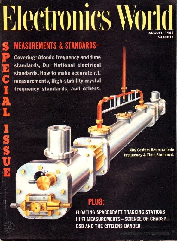
Fig. 1 - Present absolute electrical units, used since 1948. During the closing years of the 19th century and the beginning of the 20th, national laboratories were organized in a number of countries including the United States, to preserve and disseminate the units of measure; and in 1910 representatives of the national laboratories of Germany, France, Great Britain, and the United States met in Washington to compare standard resistors and standard cells whose values had been assigned in terms of their national units, and to resolve differences among the various silver voltameters. As a result of this meeting each representative returned to his own national laboratory with a group of resistors and standard cells whose values were assigned in terms of a mutually acceptable "International" ohm and volt, realized through the "reproducible" units. During the next four decades, the various national laboratories maintained their electrical units more or less in terms of these groups of resistors and cells; but by 1930 it was quite generally argued that the mercury ohm and silver ampere, on which the "International" system of units was based, were not reproducible with sufficient accuracy for scientific and technological purposes-in short, the techniques of measurement were outgrowing them; and also, unacceptably large discrepancies were showing up in comparisons between the national standards of some countries. So it was agreed that "absolute" ohm and ampere experiments would be performed at some of the national laboratories, and that the results of these experiments would be used to reassign the various national units on an "absolute" basis. At an international meeting in 1935 it was hoped that the transition to the "absolute" units could be made on January 1, 1940; but the outbreak of war in the summer of 1939 interfered with this plan.
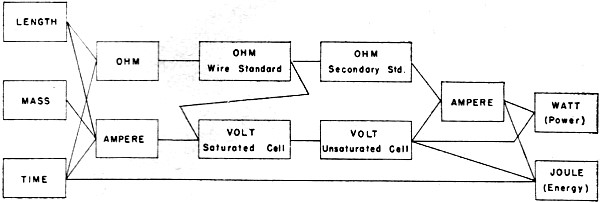
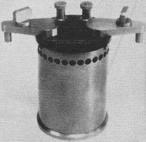
Over-all view of the NBS helical-coil balance. In the center of the coil (bottom) is a small movable coil which is attached to the arm of the precision balance. This arrangement measures change in force on the small current-carrying coil when current in the two parts of the outer coil is reversed. From the change in force and the dimensions of the coils, the exact current value in amperes is found. The transition was finally made on January 1, 1948, with changes amounting to a few hundredths of a percent. For example, the "International" ohm as then maintained at the National Bureau of Standards was stated to be 1.000495 absolute ohms, and the "International" volt, 1.000330 absolute volts. Conversion factors for the remaining electrical units can be derived in terms of these two factors and the simple relations that exist between the units. It should be noted that if the meter, kilogram, and second are used in place of the centimeter, gram, and second as mechanical units, and if the permeability of free space is assigned the value 10-7, the absolute system of electrical units becomes identical-with the practical system. Alternatively, since four arbitrarily chosen quantities can be used to define a system of electrical units, it has been suggested that the meter, kilogram, second, and ampere be used as the basis of the defined system of units, the m.k.s.a. system. This was adopted by the General Conference of Weights and Measures in 1960 as a part of the general system to be known as the Systeme International d'Unites (which is commonly abbreviated SI). Experimental Realization of Units Section 12 of the Public Law that defines the electrical units contains the following statement: "It shall be the duty of the National Bureau of Standards to establish the values of the primary electrical units in absolute measure; and the legal values for these units shall be those represented or derived from National reference standards maintained by the National Bureau of Standards." Two types of "absolute" measurements have been used in assigning numerical values to our basic electrical standards in terms of the mechanical units. The ohm is evaluated in terms of length and time; the ampere in terms of length, mass, and time. (See Fig. 1.) The absolute-ohm determinations on which our "legal" ohm are based were performed in the National Bureau of Standards and in the national laboratories of other countries. These determinations have involved an inductor (either self or mutual) of such construction that its value can be computed from its measured dimensions together with the conventionally assigned permeability of the space around it. This inductance is supplied with a periodically varying current and its reactance at the known frequency is, in effect, compared with the resistance of a standard resistor. A similar experiment could involve the comparison of a capacitive reactance and a resistance; and such a determination would have the advantage that the electrical field of a capacitor can be completely confined by a shield so that the capacitance value is independent of anything outside the shield, whereas the magnetic field of an inductor cannot be limited to be free from proximity effects. However, it is only within the past few years that a practical capacitor geometry capable of simple measurement and computation has been described in terms of a new theorem in electrostatics-the Thompson-Lampard theorem. The value of such a capacitor can be assigned with sufficient accuracy to make attractive an absolute-ohm determination in terms of capacitance; and such determinations have been made, although their results have not yet (1964) been incorporated into the "legal" ohm.
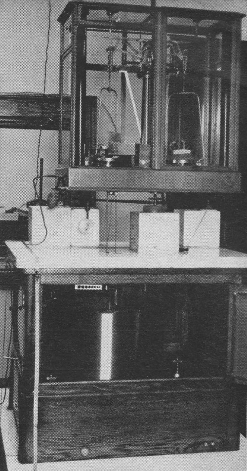
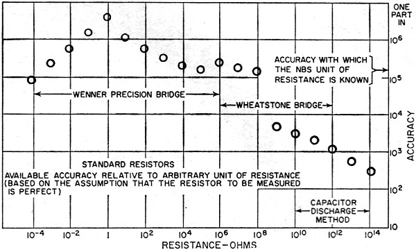
The 100-ohm-per-step dial of a universal ratio set is being checked against one of the group of 100-ohm reference standards. In an absolute-ampere determination, a pair of coils is arranged so that the force between them when they carry current can be measured in terms of the force of gravity acting on a known mass - thus the units of measure are length, mass, and time. The current, measured in absolute amperes, is passed through a standard resistor whose value is known in absolute ohms. The resulting voltage drop is compared to the electromotive force of a standard cell, and its value is assigned in terms of absolute volts. "Legal" Electrical Units The absolute measurements on which are based the assignment of the National reference standards are time consuming and require great care and skill. Their occasional repetition, to maintain surveillance on the constancy of the national standard, is desirable. But for the purpose of providing a continuing measurement capability, groups of wire-wound resistors and of standard cells constitute the National reference standards and form the basis of the "legal" electrical units. The National reference standard of resistance for the United States is a group of ten 1-ohm resistors of special construction. Their values were assigned on January 1, 1948, in terms of an international agreement based on the results of the various absolute-ohm determinations. The "legal" unit of resistance is preserved in terms of their group average, which is assumed not to have changed since the 1948 assignment. The resistors of the group are regularly intercompared to about a part in 107. In addition, our national standard is compared at regular intervals, through measurements made at the International Bureau of Weights and Measures in Sevres, France, with the standards maintained by National laboratories of other countries. The maximum net change in any of the group with respect to the group average has been a little over 2 ppm (parts per million) in the 30 years that have elapsed since the group was first set up. In the international comparisons over the past decade, the differences between our unit of resistance and that maintained by the International Bureau have never been greater than 1 ppm; and in only one instance was the difference greater than 0.4 ppm. It is believed very unlikely that the "legal" ohm-maintained in terms of the average of this group of ten resistors - differs from the defined absolute ohm by as much as 4 ppm; and there is evidence in terms of recent absolute-ohm determinations (capacitive) that the difference is no more than 1 ppm (Fig. 2).
Fig. 2. Available accuracy of various standard resistors.
Fig. 3 - Present voltage and voltage-ratio accuracies.
This large, double-walled standard 1-ohm resistor is used to maintain the standard unit of resistance.
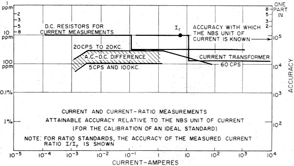
Fig. 4 - Present current and current-ratio accuracies. At that time there were no national laboratories where standards could be checked; and there was a need for "reproducible" standards that could be set up in any laboratory to duplicate the units. In 1893 the Chicago Electrical Congress fixed on a mercury column 106.3 cm. long and with a cross-section of 1 sq. mm. to represent the ohm at 0° C. In 1892 the British Association adopted as a "reproducible" ampere, the current that would deposit silver from a silver nitrate solution under specified conditions at the rate of 0.001118 gram per second. The apparatus used for this measurement was called a "voltameter." The National reference standard of e.m.f. is a group of 44 saturated standard cells (commonly referred to as Weston cells), maintained continuously at a temperature of 28 ± 0.01° C, and held at 28 ±0.001° C during intercomparisons. Eleven of the cells have been in the reference group since 1906; of the remainder, 7 made in 1932 and 26 made in 1949 were added to the group in 1955. New cells are made periodically of carefully purified materials, and are kept under the same conditions as the reference group and compared with it regularly. Thus a cell having a known history of constancy is always available for replacement, if one of the National reference group fails. The cells of the reference group are intercompared regularly and their average value is assumed to be constant. It is in terms of this group average and its 1948 assignment that the "legal" volt is maintained. Improved standard of capacitance. This design, based on a recently discovered theorem in electrostatics, allows capacitance value to be calculated directly in terms of length. This unit is regularly compared with those of other countries at the International Bureau. Over the past decade the differences between our unit and the one maintained by the International Bureau have generally been less than 2 ppm, although on one occasion (1953) the difference amounted to about 3 ppm (Fig. 3). Recently an additional means of checking the constancy of our National electrical units has become available by using a natural physical constant - the gyromagnetic ratio of protons in a sample of pure water. These elementary charged particles are continually spinning like miniature tops. Because of this spin and their electric charge, they behave like magnets and tend to align their spin axis in the direction of the ambient magnetic field. When they are thus oriented and then disturbed, they precess about the direction of the magnetic field, just as does a spinning top or gyroscope in the earth's gravitational field. This precession frequency, which we can measure very accurately, can be used to measure the strength of the field. In our experiment, the field is set up within a precisely made solenoid and can be computed from the coil dimensions and the measured current in the coil. This current is measured by comparing the voltage drop it produces in a standard resistor to the e.m.f. of a standard cell. If the measured precession frequency is constant we know that the current has not changed and therefore that the ratio of the National volt to the ohm has not changed - strong evidence that neither has changed, since it is quite unlikely that they would both drift in such a way that their ratio would remain constant. A series of measurements over the past four years indicate that the Bureau's ampere has been constant over that interval, the maximum departure from the mean value being 0.4 ppm (Fig. 4). While all available data indicate constancy of the National reference standard of e.m.f., there is evidence - both from absolute-ampere determinations and from consideration of internal consistency of the assigned values of various atomic constants-that the "legal" volt (maintained in terms of the National reference standard) differs from the defined absolute volt by about 10 ppm. Certainly there is need for further absolute measurements, and there is now under consideration an absolute-volt determination directly in terms of the amount of force that is associated with a potential difference between the electrodes of a capacitor. Capacitance and Inductance
Fig. 5. The accuracy of capacitance measurements.
Fig. 6. The attainable accuracy of inductance measurements. There are no national reference standards for capacitance and inductance in the pattern used for the National reference standards of resistance and e.m.f. However, the 1-pf. computable capacitor used in the absolute-ohm determination can be set up and measured without great difficulty; and the assignment of its value is believed to be correct within 1-2 ppm in terms of the defined absolute unit. Studies are in progress to develop stable capacitance standards in the range 1-103 pf.; and in this range, the values of "ideal" capacitors can be compared within 1-2 parts in 107. In this context, the term "ideal" means a standard which is completely stable and whose value is independent of ambient conditions. For values of capacitance greater than 103 pf., the attainable measurement accuracy falls off, and is less by a factor of about 10 at the 1-μf. level of capacitance (Fig. 5). Inductances are regularly measured at low frequencies in terms of capacitance and resistance, for example in a Maxwell-Wien bridge. In the middle range of inductance (1-100 millihenrys) and at a frequency of 1 kc., an "ideal" inductor can be measured in terms of real capacitors and resistors to about 0.01%. Measurement accuracy falls off at higher and lower values. In fact, if one were to plot measurement accuracy for any kind of quantity against magnitude, the typical shape of the curve would be a triangle with its apex (the region of best accuracy) in the intermediate range of values (Fig. 6). Accuracy of Measurement For resistance and voltage measurements, where a national reference standard is maintained, the apex of the "accuracy triangle" coincides with the value at which the standard is maintained. That this must be so is apparent when one considers that at this value one-to-one comparison or substitution methods are available for measurement, with only small differences involved. As one departs from the reference value, measurement techniques grow more involved and complicated; and the additional sources of error are present. For example, the accuracy with which a ratio can be established may need to be considered as part of the problem. Thus, whereas 1-ohm standards can be compared to 1-2 parts in 107, when we reach 10-3 ohm on one side of our accuracy triangle and 106 ohms on the other side, state-of-art accuracy has fallen off to perhaps 4-5 ppm, somewhat more than a factor of 10. Using potentiometers and appropriate voltage-divider techniques, direct voltages can be measured within 10 ppm between 10-2 and 103 volts, and standard cells (at the 1-volt level) can be compared within 1-2 parts in 107. Direct currents can be established at the 1-ampere level within a few parts in 107, and within 10 ppm for lower values down to perhaps 10-4 ampere. In the higher current range (above 1 ampere) where measurement is complicated by the heating effect of power that must be dissipated in the measuring equipment, measurement accuracy is somewhat less - perhaps a few parts in 105 up to 103 amperes. In transferring from direct to alternating voltage, an additional uncertainty is involved, amounting to perhaps 10 ppm in state-of-art voltage transfers up to 20 kc. between 1 to 500 volts. In current transfer over the same frequency span, the state-of-art transfer uncertainty is about the same, 10 ppm, in the 5-10 milliampere range where no shunts are required. The use of shunts or other circuit elements designed to carry currents of higher magnitude, involve further uncertainties because of their inductance. The total transfer uncertainty, up to about 20 amperes, need not amount to more than 0.01%. In this article, we have described and examined our National Standards of electrical measure. We have covered their derivation and maintenance, as well as assessed the present state of the art regarding measurement accuracy
Posted January 18, 2019 (updated from original post on February 10, 2015) |
|||||||||||||||