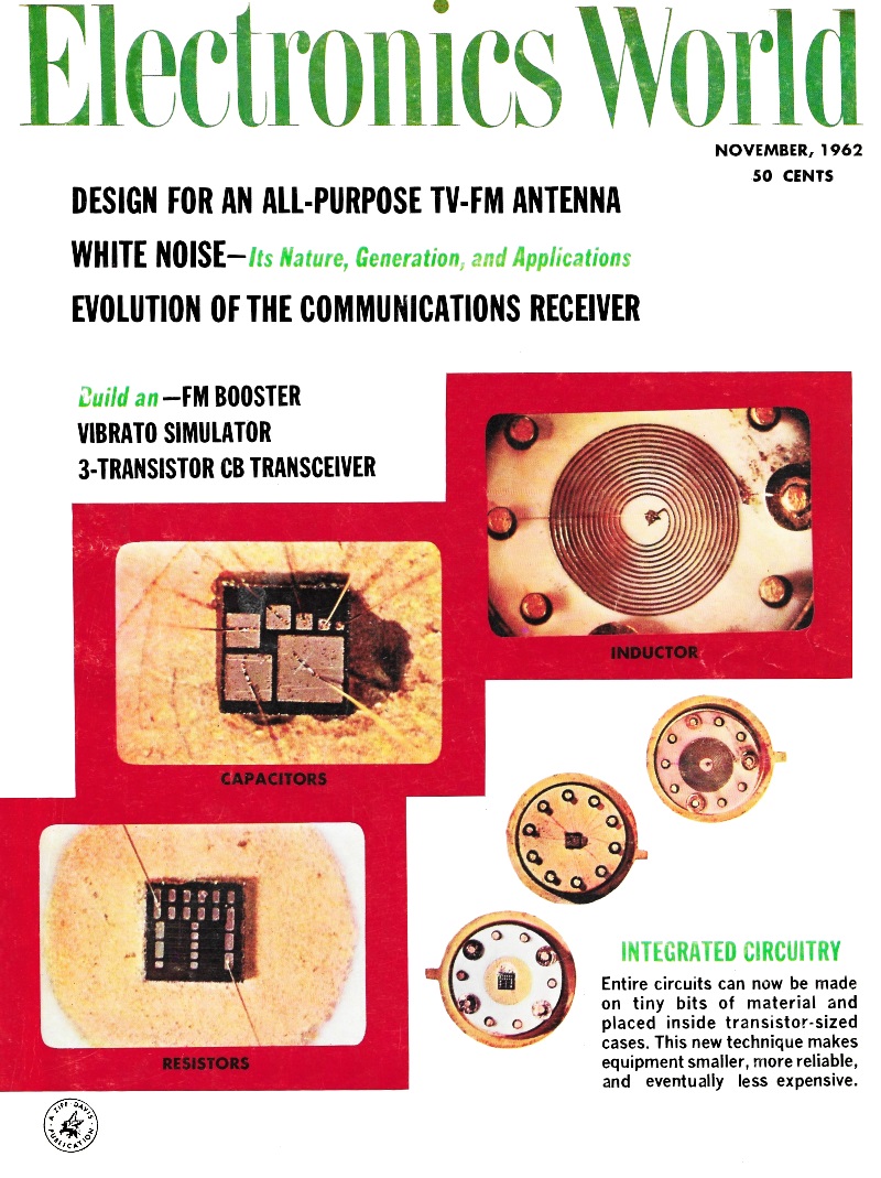
Evolution of the Communications Receiver
|
|
Author Maurice Johnson does a pretty nice job sizing up the evolution of communications receivers in his multi-part series in Electronics World magazine. He begins with the pre−World War II radio sets and works up through contemporary models. A major step in the evolution was going from simple heterodyne to superheterodyne frequency conversion; that was actually a WWI innovation. Heterodyne sets usually went from the radio frequency (RF) frequency directly to audio frequency (AF). Superheterodyne included an intermediate frequency (IF) prior to final conversion to audio, which permitted a fixed frequency filtering and amplification stage independent of the received frequency. Also addressed is the superregenerative circuit which greatly improved signal sensitivity. A shift from Morse code (digital) to audio communications drove improvement in detector technology, where the crude coherer type device was of no use. Evolution of the Communications Receiver - Part 1 - Pre-War Sets
By Maurice P. Johnson, W3TRR The history of radio reception probably began as far back as 1887 with the experiments of Heinrich Hertz in Germany. With a receiver consisting of a wire looped into a circular spark gap, he was able to detect radio signals by watching arcs across the gap. Such a primitive device would hardly inspire the technician of today; yet barely seven years later wireless communications was well on its way. In England, Oliver Lodge had managed to record Morse Code transmissions with a receiver consisting of an antenna, a tuned circuit, and a "coherer" type detector, which was essentially a glass tube filled with iron filings. Once Lodge's methods were revealed, a flurry of interest followed and "experimental wireless" activity began. The development of the vacuum tube did much to spur receiver design in the years that followed. The discovery of the Edison effect had led to the diode or "oscillation valve" of Fleming. The Fleming valve could be used to detect r.f. signals and could thus replace the crystal detector. By 1906, de Forest had added the grid to control the current flow within the diode. This gave receiver designers the triode tube, or "Audion" as it was called, which was able to amplify as well as to detect radio signals. In the radio magazines of the early 1900's, some crystal detectors and their circuits (Fig, 1A) were pictured, but there were several allusions to the superiority of the Audion circuits. Early tube manufacture was beset with problems, but designers hastened to incorporate the delicate triodes into receivers and many circuits were developed around them. One of the most popular circuit configurations to evolve was the grid-leak detector (Fig. 1B), which permitted the triode to function as a detector as well as an amplifier. Sensitivity was improved by the gain thus introduced into the receiver, but selectivity was still limited by the single tuned circuit. It will be noted that amplification is at audio frequencies since the tube gain follows the detection. Design refinements appeared as improved tube manufacture, antenna matching with an added primary coil, and audio transformers to couple the tube to the headphones. However, selectivity still suffered because of the grid-current loading on the tuned circuit.
Fig. 1 - (A) Crystal, (B) grid-leak, and (C) regenerative sets. Sensitivity continued to receive much attention. A most important forward step occurred with the invention of the regenerative circuit by Armstrong in 1914. This introduced positive feedback from the output to the detector input. which served to couple reinforcing energy back into the tuned circuit by means of a feedback or tickler coil. This resulted in tremendously increased sensitivity because of the re-amplification which took place. Control over the feedback energy involved a variable resistance shunting the tickler winding. Another regeneration control consisted of a variable plate bypass capacitor, familiarly known as the "throttle" capacitor. See Fig. 1C. Sensitivity of the detector had now been amazingly improved but the addition of regeneration added a critical operating control to the receiver. The operating point of maximum sensitivity required careful adjustment of the feedback to a point nearly sufficient to overcome the circuit losses. Any further increase in feedback caused the circuit to "spill over" into self-oscillation. However, the oscillating detector did permit "autodyne" reception of unmodulated code (c.w.) signals. The ordinary grid-leak detector and the non-oscillating regenerative detector produce an audio output only from modulated signals. Audible reception of unmodulated c.w. signals was therefore impractical since no audio output was produced. However, if two r.f. signals are applied simultaneously to a detector, heterodyne or beat products appear in the output. If the separation between the r.f. signals is equal to an audio frequency, the beat is audible. In the oscillating regenerative autodyne detector, one r.f. signal is that being received, while the beating d. signal is that developed due to feedback in the detector. The received c.w. signal produces an audio note in the receiver output. Thus the re-generative detector was useful for reception of both modulated signals as well as unmodulated code signals. Combinations of the regenerative detector coupled to audio amplifiers were developed, but the oscillating detector did have an inherent disadvantage. It acted as a transmitter as well as a receiver, radiating a signal from the antenna that caused interference in other receivers. This led to the name "blooper" for the set.
Fig. 2 - Typical three-tube regenerative receiver using ganged tuning of the r.f. and detector stages. Trimmers are used for antenna matching and for improved tracking of the r.f. amplifier stage. The regeneration control varies the screen voltage of the grid-leak detector. Another stage of audio amplification was frequently used if a loudspeaker was to be employed. An a.c. rectifier, usually full-wave, completed the set's tube lineup. Radio continued to be of an experimental nature up until World War I when transmissions were forbidden. Until then, in addition to c. w. transmissions, voice modulation had developed as microphones and modulation techniques were perfected. During the war, considerable progress was made in tube production techniques. Following the war, radio broadcasting began and radio started its invasion of the home as an entertainment medium. Although this article is not really concerned with broadcast receivers, certain developments in the receiver art were directly attributed to the demand for broadcast receivers for home use and should be acknowledged. The improved triodes were introduced as r.f. amplifiers ahead of the detector. The problem of increasing selectivity was attacked by tuning the r.f. stage, and the t.r.f. stage was born. A tuned-plate and tuned-grid load were thereby presented to the r.f. tube, but the triode with high grid-to-plate capacity was always a potential oscillator. To keep this stage from oscillating, several neutralization circuits were devised; one of the best was developed by Hazeltine in the "neutrodyne" receiver. To increase the acceptance of radio in the home and to lift receivers to a level above that of "knob-twister's delights," the tuned r.f. circuits were ganged and tracked, resulting in one-knob tuning. The t.r.f. stage was finally tamed with the appearance of the screen-grid tube with its reduced inter-electrode capacity. This obviated the need for neutralization. The demand for operation from. the a.c. outlet in the home resulted in battery eliminators, power packs, and new tube types. When all components were combined with the loud-speaker into furniture-type enclosures and cabinets, home receivers had arrived. The t.r.f. receiver still suffered from varying sensitivity and selectivity across the tuning range, and this limitation was probably the main reason for its being gradually supplanted by the superheterodyne as the broadcast receiver circuit in the years that followed. However, the t.r.f. continued to find favor for short-wave reception for a much longer time. Regenerative Communications Receivers The evolution of the regenerative detector and t.r.f. stage has been briefly covered to portray the receiver design picture up to the mid 1920's. Although the superheterodyne had been developed by Armstrong before this time, it was a more complex circuit than the t.r.f. Tubes were comparatively expensive, and factors such as initial cost and current drain made the simpler circuits continue to find application. Actually, the combination of a t.r.f. stage preceding a regenerative detector and followed by audio amplification proved to be a very practical circuit of such wide short-wave application that it probably deserves to be known as the beginning of the "communications" receiver. Many versions of the circuit continued in popularity in the late twenties, through the thirties, and at least up to World War II. Such receivers appeared in marine, aircraft, and police installations and have been used by amateurs, experimenters, and SWL's right up to the present. A familiar set of the type in the early 1930's was the Pilot "Super-Wasp." This was available in both battery and a.c. versions and tuned 500 to 14 meters with plug-in coils. An article in the January, 1931 issue of "QST" described the National SW-5 "Thrill Box" as a new design offering "single control" and "socket power" with "tuned r.f. for the sake of selectivity and sensitivity, a screen-grid detector for the sake of sensitivity," and plug-in coils to cover the bands to 10 meters. Again the emphasis was on selectivity and sensitivity as measures of receiver worth. The circuit used type '24 screen-grid tubes for the t.r.f. and detector stages and '27 tubes in the audio. The r.f. and detector were gang-tuned with a drum dial, while an antenna trimmer and regeneration control completed the panel lineup. A separate a.c. power pack was used. Variable-mu and receiving pentodes appeared and, in 1931, James Millen wrote of the application of new tubes to the famous National SW-3 receiver. This popular receiver could be used with a.c. power pack or batteries. A '35 variable-mu r.f., '35 regenerative detector, and '27 audio stage to power headphones comprised the a.c. lineup. For battery operation, these tubes were replaced with '36's and a '37. The receiver then found application in aircraft, auto, and portable installations. The three-tube receiver circuit has survived until today and is still useful for experimenters and beginners. For a time, the 30, 33, and 34 tubes were popular for battery sets and the 58, 57, and 56 became a favored lineup for a.c. use. Metal tubes appeared and a pre-World War II RCA tube manual featured the circuit with 6SK7's and a 6C5. The circuit is still of interest and a representative version with more modern tubes is given in Fig. 2. It is interesting to note that the basic circuit remained much the same from 1930 onward, the improvements being limited to utilizing the newer tube types as they appeared. Superregenerative Receivers
Fig. 3 - Basic superregenerative set using separate oscillator.
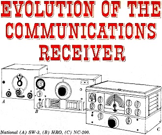
Fig. 4 - Block diagram of the basic superheterodyne receiver. Before passing on to the superhet, a variation of the regenerative detector should be mentioned. This is the super-regenerative circuit developed by Armstrong in 1922. In this arrangement, a supplementary "quench" oscillator operating in the range of 20 to 100 kc. is tied to the grid of a regenerative detector (Fig. 3). This quench voltage acts as a varying grid bias which pulls the regenerative detector in and out of oscillation at a supersonic rate. Although the quench frequency is too high to be heard in the output, the superregenerative receiver is characterized by "regeneration hiss" because of the extremely high gain under no-signal conditions. Sensitivity of the circuit is greater than the straight regenerative detector, but selectivity is poor due to the grid loading and it tends to radiate strongly. It is seldom used without a preceding r.f. stage to reduce this radiation. Some variations of the circuit use self-quenching arrangements which eliminate the separate oscillator by combining both actions in the superregenerative detector. The circuit has been useful for the ultra-high frequencies since the straight regenerative circuit is not very successful above 10 meters. The superregen was used extensively on the old 5-meter ham band in pre-World War II days. A typical 1933 circuit used a type 58 tube as t.r.f., a 24-A screen-grid type as regenerative detector with a '27 quench, oscillator, and a type 59 audio output. By 1941, a similar t.r.f. superregenerative circuit utilized the 9002 triode in the regeneration stage and the 9001 in the r.f. stage to reduce radiation and antenna loading on the detector. Such circuits were used for the 112-mc., 224-mc., and higher bands. The National Company produced the "One-Ten" receiver, which used a four-tube circuit to cover the range from one to ten meters. This used acorn r.f, tubes, with a 954 t.r.f. stage, a 955 self-quenching superregenerative detector, a 6C5 audio stage, and a 6F6 audio output. The receiver used plug-in coils to cover the tuning range. In the 1950's, superregens were largely supplanted by converters ahead of the usual communications superhets, except for some simple experimental applications. The recent advent of the Citizens Band has brought renewed activity in superregen designs. Several Citizens Band kits and factory-built receivers use the t.r.f. superregen circuit to provide good sensitivity on the 27-mc. band with maximum circuit simplicity. "Walkie-talkie" versions of this circuitry are also popular. The Superheterodyne The superheterodyne receiver (Fig. 4), which was to emerge as the most satisfactory circuit approach for communications receivers, was developed during World War I. The heterodyne principle had previously been used to produce audio signals from code transmissions. However, Armstrong's idea was to produce a higher beat frequency, at the so-called intermediate frequency (i.f.), which could then be amplified in a fixed-tuned amplifier. This i.f. amplifier was followed by a detector and audio stages. The important advantage of this circuit was that the major portion of receiver gain was at the i.f. frequency so that sensitivity and selectivity became more or less independent of the received signal frequency. Thus, the remaining disadvantages of the t.r.f. receiver had been overcome, but at the expense of a more complex circuit. While the advantages of the superhet were quickly recognized, in its early days the cost of tubes was an inhibiting factor which limited application of the circuit to only the most expensive sets. With improvements in tube performance and their reduced cost due to mass production, the superhet soon became the standard circuit for the home broadcast receiver. Some experimentation for suitable i.f. frequencies took place before the standardization at 455 kc. Present-day home receivers, portables, and auto radios are practically stereotyped in circuit, with differences in packaging and styling the major variations. However, adaptation of the superhet circuit to short-wave and communications receivers has been a continuing process that still occupies the time of receiver designers. Because of cost, some early efforts to introduce the super-het to short-wave reception were directed toward converters for use ahead of broadcast receivers. A 1931 circuit of this type featured type '24 screen-grid tubes for the local oscillator and the high-frequency mixer, or first detector, as it was often called. Plug-in coils were used and much attention was centered on the problems of making the two tuned circuits "track" to permit single-control tuning. The disadvantage of the converter was that the i.f. response of the broadcast receiver determined the over-all selectivity of the combination. Reception of code signals with the super-het required the action of a supplementary beating oscillator, the b.f.o., to generate an audible signal. This further complicated the converter approach for short-wave receivers since the b.f.o. signal properly should be applied to the second detector. In the decade preceding World War II, considerable effort was concentrated on the development of superheterodyne communications receivers. Circuit designs evolved that were tailored to the special requirements of short-wave reception. The great importance of good selectivity ahead of the second detector was recognized in terms of improved r.f. and i.f. circuits. The fact that the necessary beat method of c.w. reception produced sidebands on both sides of the carrier was attacked by Lamb in 1932, with the result that "single-signal" reception became the primary receiver feature of the day. This reception technique was made possible by the introduction of a crystal filter in the i.f. amplifier. By tuning the desired sideband into this filter passband, the crystal bridge neutralizing or "phasing" capacitor could be adjusted to null out the undesired sideband, so that c.w. signals became effectively single-sideband at the second detector. Selectivity continued to merit attention, and improved r.f. amplifiers appeared. The square-law second detector was supplanted by the linear diode detector. Automatic volume control was incorporated into the short-wave receiver. The rectified second-detector output was sampled through a long time-constant filter and was applied as degenerative bias to the variable-gain tubes of the r.f. and i.f. amplifier stages. In 1934, crystal i.f. filters for single-signal reception and a.v.c. were the latest features of receiver design. Some representative sets at this time were: McMurdo Silver's "5 series Supers," Patterson's "PR-12," RCA's "ARC-136," RME's "9D," Hammarlunds "Comet Pro," and others. The Hallicrafters name appeared on the first "Skyrider" at about this date. Receiver coverage was pushed toward 30 mc. with the surge of interest in the ten-meter band. This increased the image problem, which was approached by increasing r.f. selectivity, so that one or more tuned r.f. stages ahead of the converter became common. The 2A7 tube arrived as a combined electron-coupled oscillator and detector in one envelope, and was quickly utilized as a first detector as well as a second detector and b.f.o. Tube designs flourished and many receivers reappeared in modified form to keep up with newer tube lineups. Then metal tubes arrived on the scene, to be quickly incorporated into receivers of advanced design. Circuit refinements continued in the remaining years of the 1930's. This resulted in the decline of plug-in coils in favor of bandswitching, and communications receivers grew to be twelve- to fifteen-tube affairs with self-contained power supplies. National revised the earlier "HRO" and introduced the "NC-100," and "NC-200" receivers. Hammarlund had developed the "Super-Pro." Hallicrafters had been adding the numbers, advancing to the "Super Sky-rider" designs. Pre-War Circuit Features Examination of the circuits of good communications receivers of the period just before World War II reveals many features shared by nearly all sets. The frequency coverage was usually all-band, from broadcast to ten meters, with a few versions extended to the lower marine bands, or above 30 mc. Two-knob tuning involved a multi-band calibrated main tuning dial coupled to the ganged tuning capacitor, plus an additional vernier bandspread dial for expanding ham bands or crowded short-wave broadcast regions. The receiver front-end included bands witching coil assemblies with one or two tuned r.f. amplifiers, followed by a tuned mixer stage and the high-frequency oscillator, usually tracking higher by the i.f. frequency than the incoming signal. Outstanding similarities of all designs were the use of 456-kc. i.f. channels, single conversion, and tunable h.f. oscillators. Two or three i.f. stages were used, with considerable attention given to control of the i.f. passband, since it determined the over-all selectivity. Variable i.f. bandwidth was usually provided, with the wider bandwidths established by the amount of coupling between i.f. transformer windings. Sharper selectivity than that afforded by transformers alone was added by including a crystal filter in the i.f. path. The bridge-connected crystal, series-resonant at the i.f. frequency, had a parallel resonant notch which could be moved about in the passband by means of the phasing control. This action was useful in reducing interfering beats or signals. Being inherently high-"Q," the crystal produced a very narrow pass-band, which could be widened by external loading. Hammarlund developed one of the more versatile variable-selectivity i.f. crystal filters which found application in the "Super-Pro" and the "HQ-120" series receivers. This used steps of resistance loading to widen the filter bandwidth. With the burden of selectivity relegated to the i.f. amplifier, the r.f. stages functioned mainly to improve the image rejection. A single r.f. stage was adequate to reduce image response on the lower tuning ranges, but two stages were necessary to even approach satisfactory image rejection on the higher bands. An image ratio of 20:1 was considered to be good at 30 mc. for a receiver with two r.f. stages and a 3-stage 456-kc. i.f. A few additional comments may be made concerning other features of typical receivers. Separate mixer and h.f. oscillator tubes were used for isolation of the two circuits. Voltage regulation of the oscillator plate supply improved the voltage stability, while ceramic in coil forms, switch decks, and tube sockets, together with temperature-compensating capacitors helped to improve the frequency stability. For c.w. reception, a b.f.o. at the i.f. frequency was injected into the second detector. The a.v.c., applied to variable-mu tubes in r.f. and i.f. stages, could be disabled for c.w. signals. An "S" meter indicated received signal strength by measuring the reduction of plate current of an i.f. amplifier when the signal-developed a.v.c. voltage appeared on the grid. The diode second detector was usually followed by a peak-clipping diode audio noise limiter which reduced the effects of impulse-type noise pulses that fed through the audio circuits. A few receivers used the Lamb i.f. type noise silencer. Audio and r.f. gain controls were individually adjustable for optimizing operational gains. Few receivers tuned above ten meters, so that usable signal-to-noise ratios were determined by external noise on the antenna, and receiver noise figures of nearly 10 db were adequate. Mixer noise was not a great problem with one stage of r.f. gain ahead of the converter. Some of the receivers being manufactured at this time included the "HRO" by National, Hallicrafters' "SX-28," Hammarlund's "Super-Pro" and "HQ-120-X," the RM E "69," the "490" by Howard, and others. One or two special-purpose receivers had appeared to reach beyond ten meters. Tuning ranges went from 27 to as high as 145 mc. with acorn tubes in capacitively tuned front-ends. Such specialized communications receivers were the National "NHU" and the Hallicrafters Model "S-27." This was the state of communications receiver design when the years of World War II began for the United States. (Concluded Next Month)
Posted November 3, 2022 |
|
 A two-part series tracing circuit-design trends
of amateur and short-wave communications receivers from the very earliest crystal
and regenerative sets up to the present-day sophisticated models.
A two-part series tracing circuit-design trends
of amateur and short-wave communications receivers from the very earliest crystal
and regenerative sets up to the present-day sophisticated models. 


