Coax vs. Twinlead
|
|
The debate regarding the superiority of coaxial cable and twin-lead cable, aside from personal preferences, comes down to this: Twin-lead cable has lower loss but is vulnerable to extraneous signal pick-up and is sensitive to nearby objects in the routing path from antenna to receiver; it is also inexpensive. Coaxial cable has higher loss and is more expensive, but is significantly less sensitive to the routing path and external signal interference. In strong signal areas and/or for short runs, higher loss in coax is not an issue, and its higher cost can usually be justified for the near immunity from interference advantage. In areas where the signal at the antenna is weak and the path length to the receiver is long, twin-lead, aside from its lower cost, helps yield a better signal. The same pros and cons apply for the other direction with a signal going from a transmitter to an antenna, but this 1965 Electronics World magazine article is addressing television and radio reception. Coax vs. Twinlead
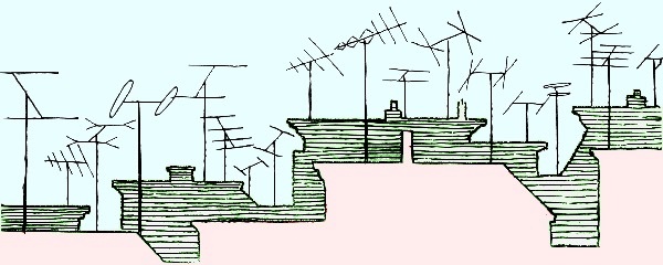
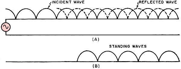
For monochrome TV reception, conventional twinlead presents no serious problems. It is low in cost and can cause less loss than coax. However, for color-TV where color adjustments become quite critical, problems do exist and many technicians are finding coax transmission lines more suitable. Transmission line is the necessary link between an antenna and a TV receiver. Although TV engineers have always preferred coaxial cable, twin lead has been used almost universally. Recently, however, many technicians began to use coax, especially for color-TV and FM-stereo. If twinlead was all right for monochrome TV, why should coax be required for color? Let's make a close comparison be-tween the two transmission lines and find out. Fig. 1 shows an antenna picking up a TV signal. Because the TV carrier frequencies are high, the wavelength is short. At channel 2, the distance between a positive-going wave-front and the succeeding one is about 17 feet. At channel 13, the wavelength is about 4 1/2 feet. As these signal wavefronts cut the antenna, they induce current to flow. At first glance, it would appear that current induced in the antenna could go down one conductor of the twinlead, into the TV receiver, and back up the other twin-lead conductor. However, things are not quite that simple. The problem is that the signal current simply doesn't have the time to complete the trip. Notice from Fig. 1 that between each positive-going wavefront is a negative-going wavefront, This negative wavefront is only half a wavelength (for channel 2, about 8 1/2 feet) behind the positive one. The negative-going wavefront induces a current in the antenna that goes in a direction opposite to that of the current induced by the positive wavefront. The r.f. signal is traveling toward the antenna with the speed of light, about 980 feet per microsecond. Nothing can exceed the velocity of light. In fact. the transmission line slows the signal down a little. Therefore. by the time the signal has traveled about eight feet down the twin-lead, the negative wavefront is cutting the antenna and the signal must reverse itself. Obviously, TV signals can't travel through transmission line like battery current. Instead, they must get to the TV set in the manner illustrated in Fig. 2. The alternator symbols in Fig. 2 represent the antenna. Fig. 2A shows the flow of current and the magnetic-field distribution during the first quarter cycle. Polarity is indicated by the arrow enclosed in the sine wave. Fig. 2B shows the entire first half cycle, at the end of which the current has traveled about eight feet down the twinlead. This brings us to the critical part of the process. As the alternator current falls to zero, the magnetic fields around the twin lead collapse. In so doing, they cut the twinlead conductors, inducing current in the original direction of current flow. It is the induced voltage that pushes the current beyond the eight feet of twinlead traversed by the original current. This process is repeated continuously along the length of the twin lead. Current builds up a magnetic field and the collapse of the magnetic field induces another current. The en-\tire package of energy, comprising the current and the magnetic field, is called an incident wave. The leading edge of each incident wave is built up by the collapsing field of the trailing edge. Note that once the incident wave leaves the antenna, it is on its own. It cannot be affected by anything happening behind it. The incident wave travels down the twinlead at about 80% of the speed of light. Fig. 2C shows the second half cycle. This produces a similar incident wave, except that current direction. and magnetic-field polarity are reversed. In other words, electron movement is opposite to that in the portion of the line just ahead. How is it possible for electrons to move in two different directions in the same conductor simultaneously? Actually, electrons travel within the conductor on the order of millionths of an inch - a mere "twitch" of electrons. In other words, electrons in the section of twinlead under the leading wavefront twitch forward, while electrons under the succeeding wavefront twitch backward, as indicated by the arrows. Standing Waves
Fig. 1 - Field pattern of a typical TV or FM antenna pickup.
Fig. 2 - How a wavefront gets down antenna transmission line.
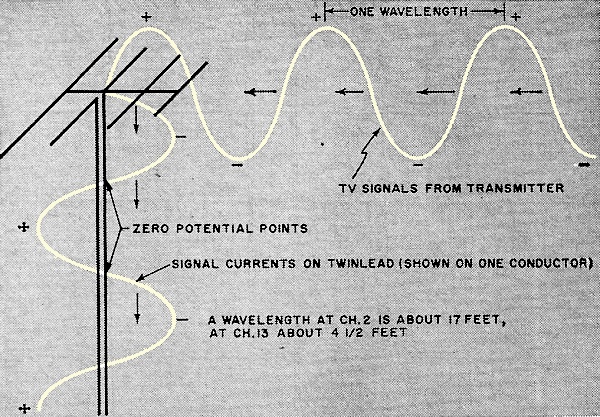
Fig. 3 - Schematic representation of transmission line shows it to be a network of inductors and capacitors. Mutual couplings, thus impedance, can be changed by external influences.
Fig. 4 - When both ends of a transmission line are not terminated in the correct impedance, standing waves are set up.
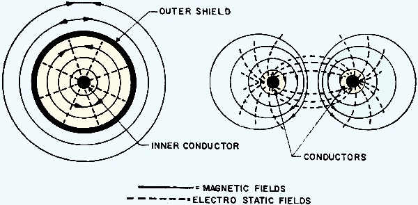
Fig. 5 - Coaxial cables are not influenced by external fields as much as twin lead. Impedance remains relatively constant. The alternator (antenna) does not "see" its final load. It sees only the half wavelength of wire into which it feeds its currents. The load at the other end of the line cannot affect the generator directly because there are points of zero potential between the generator and the load. For this reason, the law which says that source impedance must equal load impedance for maximum energy transfer does not precisely apply here. There is an in-between step. For high frequencies such as TV signals, where the line is more than a half wavelength long, the source (antenna) impedance must match the transmission-line impedance, and the transmission-line impedance must match the load (TV receiver) impedance. It is because 300-ohm twinlead is so widely used that almost all TV sets and antennas are matched to 300 ohms nominally). What makes twinlead have an impedance of 300 ohms? first of all, because every conductor shows inductive and capacitive reactances, we can come up with a representation such as the basic network (shown untinted) in Fig. 3. This figure is just a schematic representation of twin lead, but an artificial transmission line can actually be built of coils and capacitors and it will act exactly like a long 300-ohm line. As a matter of fact, artificial "delay" lines are used to time pulses in radar equipment. Not every parallel pair of conductors has an impedance of 300 ohms. (In fact, not all TV twinlead on the market has the correct impedance.) Actual impedance depends upon three factors: the size of the conductors, the spacing between the conductors, and the dielectric material used between the conductors. We've already watched a signal as it traveled down a transmission line. But what happens when it gets to the end? Suppose the end of the line is an open circuit. The TV signal will start down the twinlead. All it "sees" is a half wavelength at a time. When it gets to the end of the line a peculiar thing happens. The signal energy has no place to go. It can't just disappear. Therefore, it just starts back up the wire again, reversing its direction. While part of the signal has bounced back from the circuit end of the twinlead, more signal is coming down the line. This is illustrated in Fig. 4A. The solid line represents the signal going down the line and the dashed line represents the signal bouncing up (reflected wave). Once again, it appears that we have current simultaneously going in two ways in a conductor. Actually, you can't have two opposite currents in the same portion of the same wire at the same time, but you can have two opposite fields in the same space. That's what is happening here. What's more, these fields are passing through each other. At certain points along the transmission line. the polarity of these fields is such that they add, increasing the current conduction at these points. At other points, the fields cancel and no current flows in the conductor at these points. While the signals going up the line are moving, and the signals going down the line are moving, they always cross each other for a given polarity at the same point. Thus. the points of addition and cancellation are always the same. As shown in Fig. 4B, the resultant wave pattern does not move. Because it remains stationary, we call these waves "standing waves." So far we've discussed only open-ended twinlead. What happens if the end is shorted? Pretty much the same thing. The signal still bounces back up the line, but it is reversed in phase. While unterminated line will show a voltage maximum and current minimum, a shorted line shows current maximum and voltage minimum at the end. How can reflected signal and resulting standing waves be eliminated? We must either make the transmission line endless, or make it appear endless. Obviously, the second method is the more practical. To an alternator, an endless 300-ohm transmission line looks just like a 300-ohm load. Therefore, we can fool the alternator into thinking it sees an endless line by terminating the line with a 300-ohm load. This could be a 300-ohm resistor placed across the end of the line, but in most cases the TV-tuner input acts as the 300-ohm load. To recap, we started with a 300-ohm antenna, went through 300-ohm twinlead, and terminated the line with a 300-ohm TV set. Theoretically, the installation works just fine. The trouble is that twinlead maintains 300-ohm impedance only in free space. Fig. 3 shows what happens to twinlead under normal installation conditions. Standoffs and insulators, represented by the iron ring, couple into the magnetic fields around the twinlead. This increases both inductance and capacitance, causes an increase in losses, and greatly reduces the impedance. In fact, if the ring is crimped closed, the transmission line behaves almost as though it were shorted at that point. Similarly, a sheet of water or ice acts like a large capacitor across the line. Staples used to run twin lead along baseboards can be the worst offenders. Proximity to metal, with the resulting change in impedance also causes standing waves in twinlead. If standing waves are unavoidable, how have TV technicians been able to use twinlead all these years? Do standing waves actually make any difference in the TV picture? Standing waves cause both ghosts and signal attenuation. However, these problems have not been particularly severe for monochrome TV. Let's consider the "ghosts" first. 'When the signal sees an impedance change - or a "lump" in the line - it bounces back up the line. However, a portion of that signal eventually does reach the receiver. Because the average installation uses a number of standoffs and staples, there are multiple reflections, each arriving at the screen at a different time. The reason that we are willing to put up with these multiple-line ghosts is because they are so closely spaced. The horizontal sweep trace moves across the TV screen in 53 microseconds. Therefore, the reflected signals would have to travel over half a mile extra up and down the twin lead to cause a one-inch displacement on a 17-inch TV screen. Since the reflected signal actually doesn't travel very far, the ghosts are closely spaced, appearing more as smears. These close-spaced ghosts are not too greatly disturbing for black-and-white TV, but they can destroy a color picture. Remember, the color carrier is demodulated by a phase sensitive detector. Thus, a change in phase causes a change in color. The reflected signals not only cause ghosts, but the ghosts are the wrong color - a very annoying situation. What about signal cancellation? As an experiment, connect a piece of twinlead about six feet long to the TV-tune input terminals - in parallel with the antenna lead-in. Tune to an operating channel and then start snipping the end of the twin lead off, about a quarter of an inch at a time. Soon you'll arrive at a length of twinlead that severely attenuate the signal strength of the channel being watched, and the picture will get snowy or lose sync. What has been done is to make the line length such that the null point (see Fig. 4) of the standing wave is right at the TV-set input. This illustrates how standing waves can reduce signals. Strategically placed standoff insulators can have the same effect. Reflected signals can also ruin FM-stereo reception by attenuating the signals, causing the typical buzzes and squawk that are characteristic of weak signal reception. Fig. 5 shows a cross-section of coaxial cable compared with a cross-section of twinlead. Note that the magnetic and electrostatic fields around the twinlead conductors extend out into the space around the twinlead. This is why twinlead is susceptible to impedance changes caused by surrounding objects. Look closely at the coaxial cable representation. Like twinlead, coax depends upon the build-up and collapse of magnetic and electrostatic fields in order to conduct. The difference is in the contours of these fields. By definition, both inner and outer conductors of coax have the same center. Therefore, the magnetic fields around these conductors also have the same center. However, current always travels through the outer conductor in a direction opposite to that of the inner conductor. In other words, these magnetic fields occupy the same place at the same time, but they are opposite in polarity. Since they are also equal, they cancel each other out. The electrostatic lines of force appear only between the inner and outer conductors. They do not cancel out but are confined within the cable shield. Since no part of the coaxial cable fields appears outside the cable, it is completely unaware of its surroundings. It maintains its impedance regardless of proximity to metal or water. A commercial, weatherproof matching transformer can be used to match a 300-ohm antenna to 75-ohm coax. The transformers should be mounted as close to the antenna as possible. The coax can be taped to the mast or tied with nylon cord. At the TV set, another matching transformer is required. The coax can be secured in place with round staples. such as Arrow T-25, or ordinary fence staples. Be careful not to crush the coax, however. The one thing that can change coax impedance is a change in spacing between the center conductor and the shield. There are five good reasons why coaxial cable should be used for all color-TV and FM-stereo antenna installations: 1. Coax is Impervious to its surroundings. You can run it underground, through pipes, alongside a.c. wires, or under water, and it won't change impedance. 2. Coax won't pick up direct TV signals. This is another cause of ghosting in twin lead installations. 3. Coax is very durable. It will last about ten times as long as twinlead. 4. Coax is easy to install. There is no need to worry about avoiding metal or other wires. 5. Coax won't pick up auto or appliance interference. (Editor's Note: It should be understood that all twinlead referred to above is the conventional flat type. Many of the comparisons made do not apply to such special all-weather twinlead as Belden 8285 and Amphenol 214-103.)
Posted March 21, 2024 |
|