Ceramic Capacitors
|
|
I learned a new word in this issue of Electronics World magazine's special report on ceramic capacitors: "discoidal." It looked like a made-up word to describe something that looks like a disc. Anyway, the July 1965 issue contained a collection of articles on the various sorts of capacitors in use at the time. Other types of dielectrics covered were tantalum, glass, plastic-film, mica, paper, and metallized-dielectric. Ceramic and electrolytic capacitors were by far the most widely used capacitors during the vacuum tube era since they were relatively inexpensive to manufacture and could handle high voltages. Hobbyists who service and/or refurbish vintage electronic equipment still need this information if for no other reason than to verify component values based on color codes. It also helps to know how the electrical properties vary over temperature, frequency, applied voltage, etc., when deciding which type of modern capacitor will best serve as a suitable substitute. Ceramic Capacitors
Ceramic-Capacitor Color Code By Engineering Dept./Capacitor Products, Centralab The Electronics Div., Globe-Union, Inc. Varying composition of the ceramic dielectric can produce a broad range of temperature-compensating, high-dielectric-constant capacitors. Ceramic dielectrics are among the most outstanding and versatile of all capacitor dielectric materials. They can duplicate, and in many instances far surpass. the characteristics of other dielectrics. Their wide range of dielectric constants (K) gives them a notable advantage in microminiaturization. The K advantage which ceramics possess is only one of the inherent superiorities of this dielectric. The ability to operate over wide frequency ranges, to be functional over large temperature excursions, and to possess either linear or non-linear characteristics gives a heretofore simple capacitor giant capabilities. The ability to mold ceramic materials into numerous shapes, sizes, and thicknesses gives them both mechanical and electrical design possibilities beyond those of any other dielectric material. The development of ceramic capacitors can be traced to the German discovery in the 1870's of Rutile (titanium dioxide). Experiments with this material enabled production of ceramic capacitors with K's less than 25 in the early 1920's, but these efforts were scarcely more than a laboratory curiosity until the advent of higher dielectric constant materials. In 1936, Centralab commercially produced the first ceramic capacitor in a tubular configuration, having a dielectric constant of 100. World War II gave tremendous impetus to the development of higher K ceramic dielectric materials and implementation of the use of the disc configuration. Capacitor usage in disc form grew by leaps and bounds until the mid-50's when their usage far surpassed that of any other dielectric material. Virtually all of the ceramic used for the dielectric in ceramic capacitors can be divided into two broad categories: temperature-compensating (or low K) and high dielectric constant (high K). This latter category can be expanded into a conventional ceramic dielectric type and into a semi-conductor type, represented by such trade names as "Ultra-Kap," "Hypercon," "Magnacap," and "Transcap." Since glass and porcelain capacitors possess electrical characteristics similar to temperature-compensating ceramic, these materials will also be included in the following discussion on capacitor types. Temperature Compensating
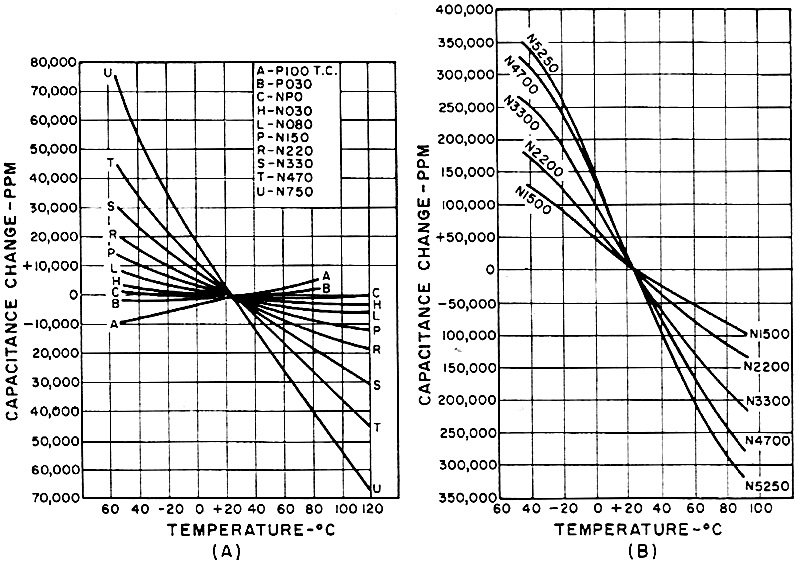
Fig. 1 - As the proportions of the capacitor material are altered, the slope of the temperature curves are changed.
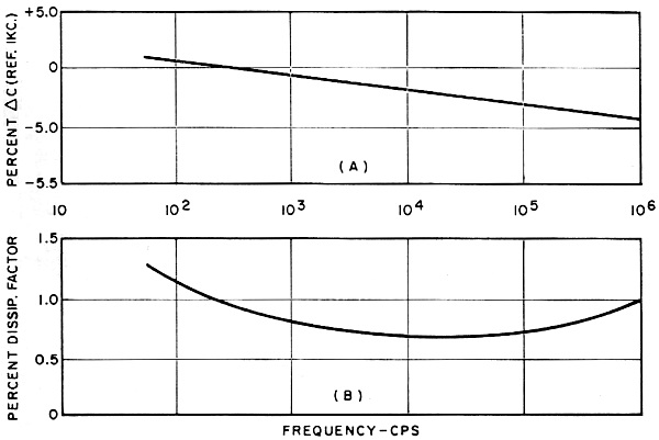
Fig. 2 - Curves show the variation in capacitance and dissipation factor with frequency, for high-K type dielectric.
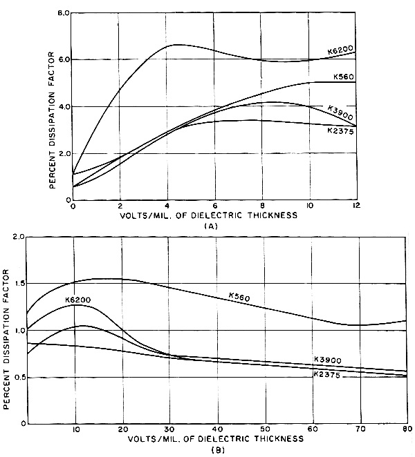
Fig. 3 - (A) The d.c. voltage coefficient of capacitance at 25°C and 1 kc. (B) The a.c. voltage coefficient.
Fig. 4 - The a.c. voltage coefficient of dissipation factor at 25°C and 1 kc. (B) The d.c. voltage coefficient.
Fig. 5 - Leakage resistance of semiconductor capacitor rated at 25 v. Ceramics possessing this characteristic have a predictable capacitance change vs temperature. This change is called temperature coefficient (TC) of capacitance and is expressed in parts per million per degree C (PPM/°C). It indicates the number of picofarads of capacitance change per degree change in temperature (centigrade). These ceramics are available with a TC from P120 (or +120) to N5250 (or -5250) and with dielectric constants from 5 to 570, generally increasing as TC becomes more negative. Standard coefficients and tolerances are available as specified in EIA Specification RS-198, and Military Specification MIL-C-20D should be consulted when required. Temperature compensation for commercial applications is specified from +25° to + 85°C. MIL Specs require measurements from -55° to +85°C, or in some cases to + 125 °C, or to the maximum operating temperature. Magnesium and calcium titanates are two of the compounds used for the temperature-compensating types. The various K levels are achieved by mixing magnesium titanate (exhibiting positive TC) with calcium titanate (having negative TC). The material proportions alter the slope of the temperature curves (see Fig. 1). These titanate materials and other compositional additive types provide a K range from 5 to 110, with temperature coefficients from positive 120 to negative 750 PPM/°C, while the extended TC series have K ranges from 100 to 570 with temperature coefficients from N 1000 to N5250. The temperature-compensating ceramics possess little or no voltage-coefficient characteristics, that is, a change of capacitance or dissipation factor with applied voltage. The effect of frequency on these materials indicates that change of capacitance and dissipation factor over the frequency range of 60 cps to 1 mc. is minimal. Glass and porcelain capacitors exhibit general characteristics similar to the temperature-compensating ceramic and also possess high insulation resistance, excellent stability, and high "Q". They are limited to temperature coefficients in the NPO to P140 range and are not available in a large variety of configurations as are TC ceramics. They are also widely used in applications involving adverse environments and where cost is not a large consideration. High Dielectric Constants Ceramics in this class are characterized by a dielectric constant ranging from 600 to 10,000, a dissipation factor less than 2.5%, and insulation resistance greater than 20,000 megohms. They do not have the stability and high "Q" of the TC type. The high-K ceramic dielectrics generally are barium-titanate modified with alkaline earth titanates, zirconates, and stannates. Barium-titanate dielectric material has a peak (Curie point) K of approximately 6000 at 120°C. The addition of small amounts of barium stannate shifts the peak to a lower temperature, and increasing percentages raise the K level. A barium-zirconate modification exhibits a similar but less marked effect. Magnesium-titanate additions produce a stabilizing effect, and although these additions reduce K level, a more linear curve is thereby produced. Typical capacitor bodies are combinations of these materials and exhibit K vs temperature characteristics whose peak or Curie point occurs at about room temperature 25°C), with K falling off on either side of this peak. Generally, the magnitude of this change will be greater for materials with higher dielectric constants. It is obvious that this change in dielectric constant vs temperature will cause the capacitors to exhibit capacitance changes which directly follow these curves. Capacitors are available such that their capacitance vs temperature change characteristics fall within established limits. In addition, these materials will exhibit capacitance changes with respect to time (aging), frequency, and voltage. Fig. 2 shows the variation of capacitance and dissipation factor vs frequency, indicating a decrease in capacitance as frequency increases. The effects of applied a.c. and d.c. voltage on capacitance are shown in Fig. 3 and on dissipation factor in Fig. 4. Capacitors using these high-K ceramics will decrease logarithmically in capacitance over a period of time. Most reputable manufacturers take these small changes in capacitance into account, and units are produced to remain within tolerance (at room temperature) for one year. It is also well to note that whenever the unit is heated it will tend to be restored to original capacitance. Therefore, aging is generally not a problem. Semiconductor Types A recent discovery utilizing advanced techniques for processing high-K ceramics led to the development of the semiconductor-type ceramic capacitor. The "Ultra-Kap," first introduced by Centralab in 1955, uses this principle. These capacitors provide capacitance values as much as 100 times greater than those attainable through the use of conventional ceramic dielectrics, achieving levels heretofore available only with electrolytics and film-type capacitors. The economy and compact size of these semi-conductor units resulted in their widespread usage in transistor circuits for bypass and coupling applications. They are most suitable for operation in the audio-frequency range, and the voltage ratings of these devices are from 3 to 25 volts. All capacitors of this type will exhibit lower insulation resistance than standard ceramic types, with insulation resistance decreasing with applied voltage. They are therefore best suited for use in low-impedance circuits where this low resistance will not cause loading problems. Fig. 5 illustrates the minimum leakage resistance of this particular type of capacitor rated at 25 volts. Application Considerations The TC type of ceramic dielectric capacitor is essentially linear and therefore ideal for use in tuned circuits to compensate for inherent impedance changes. In a receiver, this compensation can be added to the oscillator circuit to effect drift compensation throughout that portion of the receiver which is dependent on the oscillator frequency. The i.f. amplifier drift can be controlled indirectly in this same manner. The linearity and tolerance of the temperature coefficient are slightly influenced by the physical configuration and may be noticeably influenced by the metallic mass in contact with the ceramic. For this reason, even though the ceramic can be fabricated in a variety of shapes, the disc or tubular style is most suitable for use in critical temperature-compensating applications. Standard compensating disc capacitors are available in sizes ranging from 3/16" to 1" in diameter with voltage ratings up to 6 kv. d.c. Tubular capacitors are generally available in 1 kv. d.c. or less. In addition to temperature compensation, the stability, high "Q," and high insulation resistance (low leakage) associated with this ceramic make it an ideal general-purpose, high-quality capacitor for use in tuned circuits, oscillators, high-frequency filters, r. f. power applications, or any other electronic circuit requiring high "Q" stability.
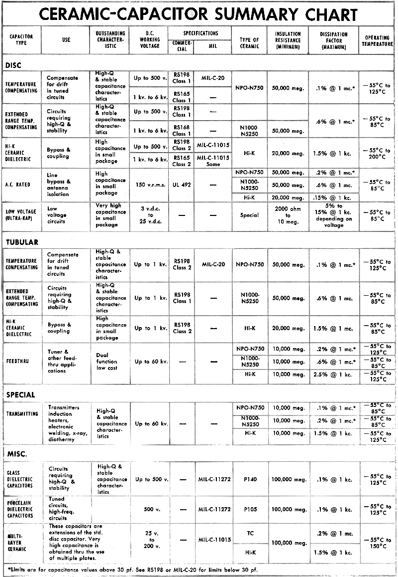
Ceramic-Capacitor Summary Chart Feedthrough capacitors are a combination of bypass and feed through that enables the designer to run leads through the chassis and simultaneously bypass. Both TC and high-K materials are used in the fabrication of these units to provide very low or very high capacitance as required. They are produced in physical sizes ranging from 1/8" in length to over 8" in length and voltage ratings ranging from 50 volts to 60 kv. d.c. Conductor current-carrying capabilities can be as high as those required for broadcast transmitters. Feedthrough capacitors are available in either tubular or discoidal forms. These latter types are considerably more expensive than the tubular configurations. Discoidal types tend to exhibit more linear attenuation characteristics in the 500- to 1000-mc. frequency range. Standoff capacitors are available in disc or tubular configurations. Tubular standoffs are used in such low-frequency applications as tie points and chassis bypass. Disc standoffs find use in high-frequency applications where lead inductance must be minimized. Special high-voltage capacitors for induction heaters, x-ray, diathermy, and r.f. applications where high-frequency and high r.f. currents are encountered, such as plate, coupling, tank, and bypass functions, utilize the desirable characteristics of TC ceramics. High-K materials can also be used in those applications where no specific temperature coefficient is required and where dielectric losses are inconsequential. These devices are designed for specific applications but in most cases utilize variations of four basic shapes, which are cup, double cup, slug, and cylinder. Voltage, current, frequency, and mechanical considerations are some of the factors which influence the final capacitor design that is to be employed in a given circuit. Capacitors of either TC or high-K dielectric (as listed by UL) can be used as a.c. line bypass or for antenna isolation applications in commercial receivers.
Posted September 26, 2022 |
|