Another Day in the Shop
|
|
If you are a fan of John T. Frye's "Mac's Service Shop" series of technodrama™s, then you might also appreciate this short-run stories by Bob Eldridge titled, "Another Day in the Shop." Up through maybe the early 1980s, every town had at least one electronics service shop for taking care of televisions, radios, record players, tape recorders and players, cameras, computers, and just about anything else that might be fixed at less cost than buying a replacement unit. In the 1940's through the 1960's, there was often good money to be made not only with in-shop repair but also with doing house calls for repair and installation. Electronics magazines of the era were filled with both self-help and tips for the professionals regarding troubleshooting, use of test equipment, how to deal with customers, etc. Electronics World even ran for a while a feature that suggested types and quantities of replacement tubes, capacitors, and transformers to keeps on hand based on collected industry statistics. I don't remember why I specifically chose this episode of "Another Day in the Shop." Students Jack and John make headway on their own, but learn more from Tommy's experience.
Editor's Note: High on the list of articles readers told us they liked last year was Eldridge's "A Day in the Shop." It involved a couple of student technicians who, in return for some miscellaneous chores, were permitted to nose about an established service shop to pick up what they could from experienced trouble-shooters. Into this story was woven much, practical bench know-how. Using the same cast of characters, the same author matches his first performance here. Every once in a while Jack and John, a pair of up-and-coming student technicians, come in to help out in our shop. They do a useful job in routine cleaning and checking chassis that are ready for servicing, meanwhile keeping interested eyes on Tommy, our benchman. Tommy, for his part, takes time out once in a while to explain just what he is doing, and why, with the sets on the bench. Tommy phoned in one morning recently to say he would be coming in to work half an hour late. Seizing the opportunity, John piled right in checking the tubes on an Emerson chassis from a model 720D.
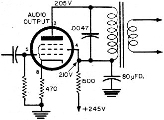
Fig. 1 - Two G-E receivers using this circuit exhibited similar symptoms. He likes to have the set running while doing this, because he hates waiting for each tube to warm up from dead cold in the tester. He used to have troubles sometimes, when he pulled the tubes in the wrong order, but now he plays it safe and removes the rectifier tube first, leaving it out. As he says, "If there's no 'B+' in the set, you can do what you like with the tubes without harming any because you have unthinkingly pulled the one that drives it." Anyway (to get back to the Emerson) when John started pulling tubes for testing, the first one attended to after the rectifier was the 6V6 audio-output tube. He noticed that it wasn't as blistering hot as he had expected and, being a methodical sort of fellow, he wrote on the check-out slip (which already bore the message, "No sound, not tubes," contributed by the outside technician) a note of his own: "6V6 checks normal but doesn't get hot in the set." Now one of the useful chores the two boys do is to hunt out the schematic for each set awaiting service. A look at the audio-output circuit on the schematic made John feel that this one should be so easy that it wasn't worthy of Tommy's august attention. John belongs to the "play-it-safe, static-test-first" school of servicing, so he set to work with the ohmmeter and in two minutes flat he came up with an open 470-ohm cathode resistor (see Fig. 4). He soldered a new resistor in place just in time to hand over the set to the late-arriving Tommy for a routine check. Except for a minor adjustment to the phasing coil, the set performed dead on the ball. Thus the first job of the day was on the hot-run bench by 9:45 a.m. No Vertical Sync Meanwhile Jack had been preparing a Majestic 110 chassis. The job sheet bore the legend "No vertical lock." The only tubes weeded out by Jack's efforts on the tester were a couple of 6AU6's. Have you noticed that the 6AU6 is often a candidate for replacement in sets where all other tubes are still going strong? On the bench, the set performed just as noted. Everything was fine except that the picture would roll up or down without even hesitating as it went round for another turn. "Well," said Tommy, "what can we see? The oscillator is capable of running at the correct speed and the sync separator must be popping out pips all right, or the horizontal would be haywire. There's not much in between the sync separator and the oscillator except the integrator network, so we may as well tack in a new one." (The circuit is shown in Fig. 2). This proved to be a bad guess and the fault remained unchanged with the replacement printed-circuit network in place. "Whip it out," said Jack, "and I'll put it back in the drawer."
Fig. 2 - The primary defect in this Majestic circuit was easily found and cured. However, an afterthought led to a recheck with interesting results. Another, hidden fault was found and cured!
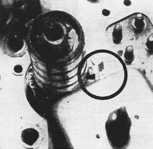
Fig. 3 - The circled ground strip, outside the tube shield, may mean trouble. "Oh no we don't," reproved Tommy, "we leave it right there until the trouble is found! What if we should have two faults at the same time, one maybe caused by the other? We leave any substituted parts in the circuit, then take 'em out one at a time when the set is working properly. What is there left to check now?" he continued. "A couple of capacitors and the 33,000-ohm resistor. It's easier to measure the resistor, so let's start with that." The ohmmeter registered the resistor as being about 35,000 ohms so the clipped end was soldered back in place and one end of the .0022-μfd. capacitor (input end of the integrator network) was disconnected. "Check it with the ohmmeter," said Tommy. "It would have to be shorted or leaking badly to produce a fault like that. If it was open, the lock would be more or less normal." The capacitor showed a dead short. Jack was puzzled to see Tommy replacing the 33,000-ohm resistor, after soldering in a new .0022-μfd. capacitor and the original integrator network. "Well," explained Tommy, "that's a matter of safety first, really. 'B+' current has been running to ground through that resistor and it may have been damaged in the process. You know how the boss feels about callbacks!" John was scribbling on a piece of paper. "Look here," he queried, "doesn't 135 volts across 33,000 ohms only produce half a watt anyway?" Tommy looked thoughtfully at the schematic. "Bet you a coffee break there's much more than that across it sometimes." He attached the probe of the v.t.v.m. to the "hot" end of the resistor, clipped the common lead to the chassis and switched on the set. Up and up swung the needle to read nearly 400 volts and then it eased slowly down to settle at 120 or so. "Let's go!" exulted Tommy (who seldom loses a bet). "What would you expect from a directly heated rectifier feeding a pile of indirectly heated tubes?" John trailed along on the way to the coffee shop, looking in bewilderment at the schematic. When they were settled in the booth he could contain himself no longer. "I don't get it!" he blurted. "What's this midget relay thing for then?" (RL1 in Fig. 2) Tommy took the schematic and studied it in silence. "That's a good question," he finally admitted. "We'll have another look when we get back to the shop. Let's forget it for ten minutes." Back on the bench the mystery was speedily solved. The 0.0047-μfd. capacitor across the midget relay contacts was completely shorted. "That was a bit of luck," said Tommy, when a new component was in place and the set was on test. "I think probably that was the original fault, and the 0.0022 went down as a result. I don't think you should pay for the coffee after all, John - the boss should! We might have had a sticky callback on that one but for your curiosity!" As we said - Tommy seldom loses a bet! Two with the Same Chassis The boys had readied two G-E "Stratopower" chassis next for attention, each with more or less the same symptoms. The first one was way off horizontal frequency and could not be corrected by adjustment. The other one could just be brought to the correct horizontal speed, with the oscillator slug unusually deep in the coil, but sync was then very unstable.
Fig. 4 - First job of the day, handled by John, involved this Emerson circuit.
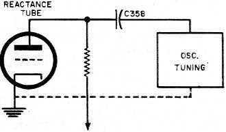
Fig. 5 - The reactance tube is in shunt with the oscillator tank, through C358. "Let's tackle the totally wrong one first," said Tommy. Like most technicians, he prefers the definite failure to the marginal one. "There's a beautiful schematic for this model, with waveforms and voltage and resistance measurements all over the place. Make a check with the v.t.v.m. on those two 12AU7 bases. Don't forget to short the antenna terminals to keep the local signal out of the set while you are measuring." John undertook the job and soon came up with a list of readings that showed the only serious discrepancies from the normal voltages were on the cathode, grid, and plate of the phase detector (Fig. 1). These points were all slightly positive, instead of being from 4 to 6 volts negative as called for in the manual. "What now?" asked Jack. "Well, according to the circuit diagram," said Tommy, "there is nothing connected to these points that could produce positive potential. That resistor R356 goes away to the grid of the oscillator, which is bound to be negative: the grid current flowing in an oscillator tube produces negative voltage at the grid terminal. Change the 12-AU7 first, just in case there's something wrong that didn't show up on the tube tester." With a new tube in the socket and the fault still present, John was studying the schematic. "Maybe that 3300-μμfd. unit (C368) from the sync section is lacking," he offered. Tommy looked at the list of voltages on the bench. "I doubt it because, if it was, you would expect to find pin 8 more positive than pin 6. It's closer to the point of connection you see. But we can't be sure of that, so clip it and have a look." "No change," reported John. "Maybe I can follow up this 'most-positive-point' idea. The most positive voltage is on pin 6. It can't be coming through the 100,000-ohm resistor (R358) because pin 8 is on the other end of that. The other end of the 1-megohm job (R355) is pin 2 of the other 12AU7, and that's reading negative. What about this 10,000-ohm fellow (R358)? "Whoops!" He grinned happily. "Now I think I'm getting somewhere. This point is more positive, so I can follow along through the 6800-ohm resistor (R365). Yep! That's even more positive! Now we come to what ought to be a dead end, a 300-μμfd. capacitor (C352). The capacitor has the same voltage at both ends, so I guess he's the culprit." "Dead on the ball," approved Tommy, "and that's the best way to approach a fault like that too. Put a decent capacitor in there, one of those 750-volt types. I'd better give the rest of the set a check over I guess. Hey!" he erupted a few minutes later, "Who checked these tubes." "I did," admitted John, "what's wrong?" "See those shields?" Tommy pointed to the i.f. strip. "You must tuck those little grounding strips inside the shield (Fig. 3) when you replace it, especially on this particular model. It has a tendency to take off into oscillation if those tubes aren't properly shielded." The Second G-E Chassis Jack had been quietly making a voltage check of the second chassis and now came up with a list that practically matched the figures on the schematic. "That doesn't get us far, does it?" he observed disappointedly. "I guess this one needs a different approach - and I was looking forward to playing Sherlock Holmes myself on this one." "Don't worry," said Tommy, "there are other ways of bringing the fault to justice without tracking him everywhere he goes. Let's look for some more evidence." He picked up the low-capacitance probe and turned up the intensity control on the scope above the bench, "Let's have a look for the sync pips coming through from the clipper circuit." He attached the probe to pin 8 of the phase detector in Fig. 1. "Note we have plenty of spike from the sync department which disappears when we tune off-channel. Always a good idea to remove the signal temporarily to make sure it is the sync pulse you are looking at, rather than some induced signal from the high-voltage section. And you can see the saw-tooth there from the horizontal-discharge tube. Better check along that line as John did with the other set. We'd look rather foolish if it was the same thing and we went batting off on some other tack." This was done, but it turned up nothing. "Now look here," said Tommy, "I think the best way here would be to sift the evidence through, exhibit-by-exhibit in the routine, component-check method. Check each part in the grid circuit of the reactance tube and then those between the reactance tube and the oscillator grid. I'm going to nip out for an early lunch." When Tommy returned, the set was working merrily on the bench, its horizontal hold as stable as a rock. "It was this 470-μμfd. capacitor, C358," reported Jack. "It has no capacitance at all according to your checker." "What does that capacitor do in the circuit anyway?" asked John. "I don't know much about this reactance-tube business." "Well," explained Tommy, "you can regard the reactance tube as being in parallel with the oscillator tuned circuit, like this (see Fig. 5). Now the capacitor that went open was coupling the reactance tube to the circuit so, with it open, the reactance tube might as well not be there for all the good it does. Under such conditions, when the oscillator drifts off-frequency, the reactance tube is not able to change the phase of the circulating currents in the oscillator tuning network to compensate for the drift ... what was that you said, John?" "I just said, 'I pass,' " mumbled John_
Posted August 20, 2018 |
|