The Silent War: Electronic Spying |
|
Ah, those were the good old days, when governments used their limited reconnaissance ability to spy on people, places, and things deemed to be a clear and present threat to the well-being of country. In 1964, during the height of the Cold War, collecting and interpreting communications data was still a very human-intensive chore, so assets were necessarily allocated based on highly strategic targets. Today, data collection collection, storage, and analysis is cheap and is done mostly unattended by humans until a red flag goes up. The possibility of a nuclear attack from the Union of Soviet Socialist Republics (U.S.S.R.) was a very real and even likely possibility. The strategic advantage of a first strike was immense, so it was to the world's advantage to monitor and react as quickly as possible. The Soviet Socialists (and their worldwide cadre of sympathizers) liked to propagandize about being concerned that the U.S. would nuke them, but anyone with a functioning brain knew the Free World had no interest in initiating a nuclear war. Unlike the unfortunate citizen proletariat of Communist, Socialist, Marxist countries, the rest of us could imagine the hope for a prosperous, happy future based on hard work and ambition. The Silent War: Electronic Spying Electromagnetic reconnaissance is one of the best guarantees against a sneak attack on the U. S. or one of her allies. It's also vital for effective arms control. By John M. Carroll, Managing Editor
Action in the North Pacific. Two Soviet Badger reconnaissance bombers that flew over the attack carrier Kitty Hawk (CVA-63) are escorted away by a Navy F-4 Phantom II (not shown) and an F-8 Crusader. The twin-jet Badger is used by both the Soviet Navy and Air Force. Its official name is the Tupolev TU-16. It has a 3,975-mile range. Electronic Spying Mission Every Wednesday at 0700, N. N. Petrov, Captain Third Rank of Naval Aviation, takes off in his twin-jet Tupolov TU-16. He circles the pine-barrens of the Kamchatka Peninsula as he climbs to 13,000 meters, then comes about to a course of 045, true. Only an observer who has seen a dozen enlisted men climb into the midsection of the bomber would know there is something different about this plane. It is a ferret, one of dozens of Soviet, British and American aircraft that regularly patrol the frontier that separates East from West, playing the serious and dangerous game of electromagnetic reconnaissance. An hour after takeoff Pavel Ivanov, the senior radio mechanic, comes in on the public-address system to announce an intercept. Ivanov is covering L band from his console. He recognizes the five-times-a-minute beep of AN/FPS-24 search radar. Minutes later, the radio mechanic at the X-band receiving position picks up the high-pitched squeal of tracking radar. It is time to turn now and follow a dog-legged northward course that will take the big plane east of Gambell on St. Lawrence Island and on toward the polar ice pack. Hours later, the plane will return with a dozen reels of magnetic videotape and log books bulging with intercept reports of U. S. radars, ionospheric sounders and vhf communications signals, all to be sent to the Signal Intelligence Service in Moscow. The incident is fictitious, but such events happen daily. Not only off Alaska but on both sides of the Iron Curtain - along the borders of East Germany and Czechoslovakia, the coasts of the Adriatic and Black Seas, the jungles of Southeast Asia, the shoreline of Communist China and the white beaches of Cuba. Soviet ferreting seldom breaks into the news the way U.S. ferreting does - that is, by having one of their ferrets shot down. The main reason U. S. guns hold their fire when Soviet planes intrude is that many Polish and Czech defectors have escaped in military aircraft. But there have been at least 90 Soviet intrusions into West Germany during the last two years. Soviet planes have flown over the U. S. Pacific Fleet several times, and regularly patrolled waters off Alaska. On one occasion, two planes flew over parts of Alaska itself. Soviet trawlers off the U. S. coasts carry an undue amount of electronic equipment for just fishing. There is also a fairly general presumption that the Soviets have launched spy satellites in orbits over the U. S. Governments don't like to talk about electronic spying - they seldom even acknowledge that it exists. But exist it does, and every time a plane is shot down along the Iron Curtain there's a chance it was engaged in gathering information electronically. Since 1950, a total of 26 United States planes have been forced down or shot down along these frontiers, and 108 airmen have lost their lives or their freedom. Major powers conduct electromagnetic reconnaissance, or ferreting, to keep track of a potential enemy's new electronic systems and his deployment of men and materiel. This information is essential in guiding electronics research and development, establishing logistic requirements for perimeter defense, and planning to evade, destroy or jam an enemy's electronic defenses. Some disarmament experts also see electronic data-gathering as a tool for keeping the peace. Clues from the News Electronic intelligence, or the suspicion of it, popped into the news several times recently. First a North American T-39B Sabreliner with three Air Force officers aboard was shot down over East Germany. This type of jet trainer has been equipped for special radar training missions, but its use specifically for electronic intelligence has never been disclosed. Next, a Douglas RB-66 Destroyer, a plane often used for electromagnetic reconnaissance, was lost in the same general area. Later there was an announcement that Martin RB-57 Canberras had been used for high-altitude overflights of the Chinese mainland. And then there was President Johnson's disclosure of the existence of the A-11, a high-flying supersonic twin-jet capable of replacing the U-2 for overflights, even of the Soviet heartland. There are also reports that electronic-intelligence versions of the Samos photographic reconnaissance satellite have been launched in polar orbits. Soviet Restraint Undoubtedly the Soviet Union also gathers electronic intelligence. A few years ago there were rumors that a Russian electronic reconnaissance plane had crashed off northern Canada. Why do so few Soviet ferrets become casualties? One reason may be superior restraint by Soviet crews. U. S. forces characteristically operate with everything turned on that can make a radio wave. For that reason, flights 100 miles off shore can be highly productive of electronic intelligence. But the Soviets typically hold back their electronic transmissions until the last minute, and it may require actual intrusion of their air space to intercept the electronic Orders of Battle - such as tracking radar, fighter-director radar, ground-air missile command signals and ground-air and air-air communications. Active and Passive Measures Electronic countermeasures, of which electro-magnetic reconnaissance is only a part, divide neatly into two parts: passive measures, or reconnaissance, and active measures, or jamming. Jamming attempts to prevent the enemy from using his electronic equipment by either saturating it with noise (barrage jamming) or by deceiving it with intentionally misleading signals (beacons, repeaters, inverse amplifier, gate stealers and track breakers). Reconnaissance merely establishes the location and electromagnetic characteristics, or "signature" of enemy transmitters. Electromagnetic reconnaissance plays a major role in strategic and tactical countermeasures. In strategic ferreting the object is to locate and identify potentially hostile transmitters including radar, communications, missile guidance and navigational aids. These are purely passive electronic countermeasures. In tactical ferreting, on the other hand, the object is to determine what electronic weapons are being used by an enemy and to determine what countermeasures to employ. In tactical reconnaissance analysis of data must be carried out while flying over the target area. In strategic uses. analysis may take place in a laboratory many miles from the interception site.
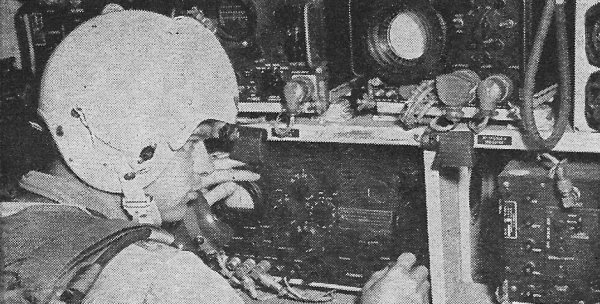
Raven position No.1 of an RB-66C. The Electronics Warfare Officer is searching for radar signals with an Apr-14 intercept receiver. Next to it is an APR-8B panoramic intercept adapter. Top row of equipment consists of another APR-8B, an ALA-5 pulse analyzer, an ALA-6 direction finder and an aircraft instrument panel. Most of this gear is of late World War II vintage. Technically the objectives are the same: capture the signal, determine its frequency, type of modulation (including pulse repetition frequency, pulse width and switching mode, if any), antenna characteristics (including beam width and pattern, rate of rotation. switching mode and polarization), and bearing. A major controversy in strategic electronic reconnaissance revolves around techniques of signal analysis. Ever since wideband videotape recorders came into being, there has been a tendency to capture all signals indiscriminately and to rely on analysis officers to identify the individual signals and correlate them with positional information. But as the number of potentially hostile radars has multiplied and frequency control has improved, it has become all but impossible to sort out the signals. As a result, many tapes recorded at great risk have been, as far as their actual strategic value is concerned, just so much junk. Thus there is a movement these days to do more analysis in flight of even strategic information, and planes like the Lockheed RC-130 Hercules have become flying laboratories. Receiving Enemy Signals
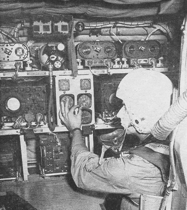
Raven position No.2 - there are four. The officer is correcting the altimeter reading on his instrument-panel repeater. The repeater panel, sandwiched neatly between two ALA-6's contains a compass, air-speed indicator, altimeter, cabin-pressure indicator, clock and latitude-longitude indicator. Bottom row contains another APR-14 and APR-8B. Top row holds three ANH-2 wire recorders, the AIC-10 interphone control panel, and an emergency oxygen bottle. Newer gear performs the annotation function automatically.
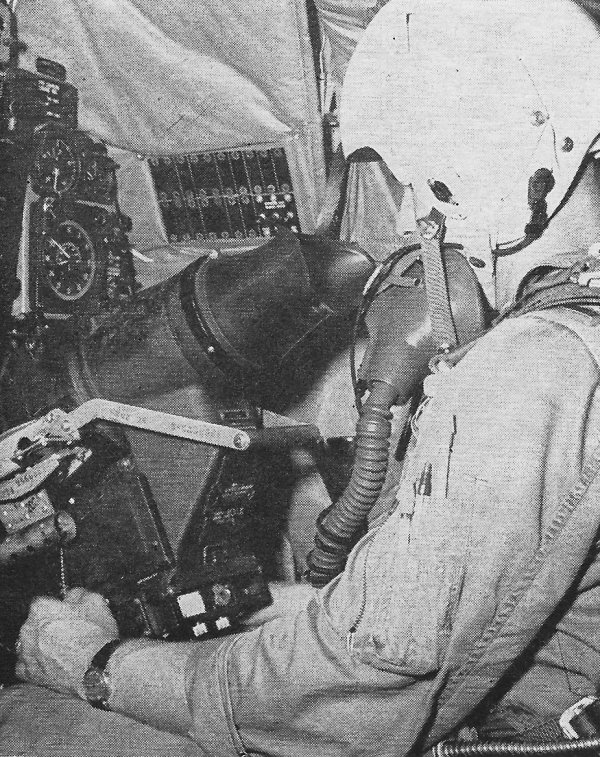
Navigator - also on the EMR team. This navigational radar scope helps establish the position of the Air Force RB-66C Destroyer in the air. Above the scope is an N-1 aircraft compass and above the compass are a dial and a clock. The first objective electromagnetic research is to receive or intercept enemy signals. There are two approaches to this problem. The first is to scan throughout the frequency band of interest using a relatively narrow-band microwave receiver. The second approach is to use a wide-open receiver that responds to all signals within the band. In fighter aircraft, ferret receivers are usually channelized because such receivers can be made small and light. On large bombers, search and lock-on receivers are used. They sweep a band, locate an intercept and lock on. Until now, most lock-on schemes were analog in nature. They simply located a signal above a certain threshold and used a servo system to tune to it. Newer systems are being digitized - often with microelectronic circuits - and can be programed to lock only onto signals possessing certain predetermined characteristics. Lock-on capability is important in both strategic and tactical reconnaissance. In the tactical situation the electronic warfare officer must identify dangerous signals such as tracking radar, and go about jamming them. In the strategic situation, the operator of the electronics equipment frequently wants a longer look at an interesting target to log it properly in his report. During World War II and the Korean conflict, receivers such as the RDO, SPR-2 and APR-4 operated in the scanning mode, using tuning motors to drive butterfly tank circuits. But the tuning process was slow, spectral coverage was limited and poor selectivity of the tuning circuits led to many spurious responses. New Uses for Old Gear Operational weapons are frequently a generation behind the best materiel available. World War I was fought with Krag rifles and borrowed Lee-Enfields even though the Springfield was officially adopted in 1903. So it is with electromagnetic reconnaissance gear. The workhorse of the tactical Air Command is the RB-66. This plane is slated to be replaced by the mach-2 RF-46 but will be around for a long time. Right now the RB-66 uses the APR-9 as its receiver for electronic intelligence. This equipment came out in 1945. Although some APR-9's have traveling-wave tube front ends, the operational units use a plain old tuned cavity. However, the APR-9's are being replaced with APD-4's. The four is a semiautomatic system utilizing wide. open frequency-discriminating receivers. It records' everything on 35-millimeter film for later processing and analysis. Each wide-open frequency discriminator receiver covers a certain channel. The receivers do not have search-and-lock-on capability because their function is just to listen in, not to defend the aircraft or provide an electronic countermeasures. The system may also be used for radar direction-finding. One of the largest ferret systems in use is called the ASD-1 It is flown in RC-135 jet tankers of the Strategic Air Command. It was built by the Air Force's Aeronautical Systems division and has both manned and automatic positions. It is much too big for either the Tactical Air Command or the Navy. Operational reconnaissance gear lags badly behind the equipment now in research and development. The USD-7 exists only in prototype. YIG-TWT-YIG receivers have been manufactured in only limited quantities. Practically speaking, the U. S. has made little progress in this field since 1945. Wide-Open Receivers These early intercept receivers had little advantage over a wide-open receiver. A wide-open microwave receiver consists of an antenna, crystal detector and video amplifier (A). It may be possible to pick up signals 50 decibels below one milliwatt with such a receiver. A modern example of a wide-open receiver is the tail-end radar detector.
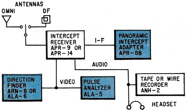
Electromagnetic reconnaissance equipment like that used aboard RB-66 bombers of the Tactical Air Command. In addition to having relatively low sensitivity, the wide-open receiver gives no indication of the frequency of the intercepted signal. It is necessary to record the receiver output on magnetic tape, together with some baseband reference signal. Later an analysis officer must laboriously scan short random samples of the tape, using a variable narrow-band filter and recorder to isolate each frequency component on the tape - and Heaven help him if there is any intermodulation present! The wide-open frequency discriminator (B), called the wideband high intercept probability receiver, is sometimes referred to as WOFD or WHIP. This discriminator adds an indication of frequency to the wide-open receiver. A signal is introduced into the wide-open receiver and split into two branches. Each branch includes a tuned circuit. In one branch the tuned circuit is responsive to the low end of the frequency band being measured, while in the other branch the tuned circuit is responsive to the high end. The outputs of the two branches go to different sets of deflection plates of a cathode-ray oscilloscope, and the angle between the two oscilloscope traces may be interpreted in frequency. This arrangement may be used to indicate phase instead of frequency. When used with two directional antennas, it can indicate the direction of the enemy transmitter. Tuned Front Ends The invention of the traveling-wave tube changed the concept of receiver design. This tube could cover with uniform response an octave of bandwidth. Furthermore, portable video recorders could capture the output of these receivers on magnetic tape.
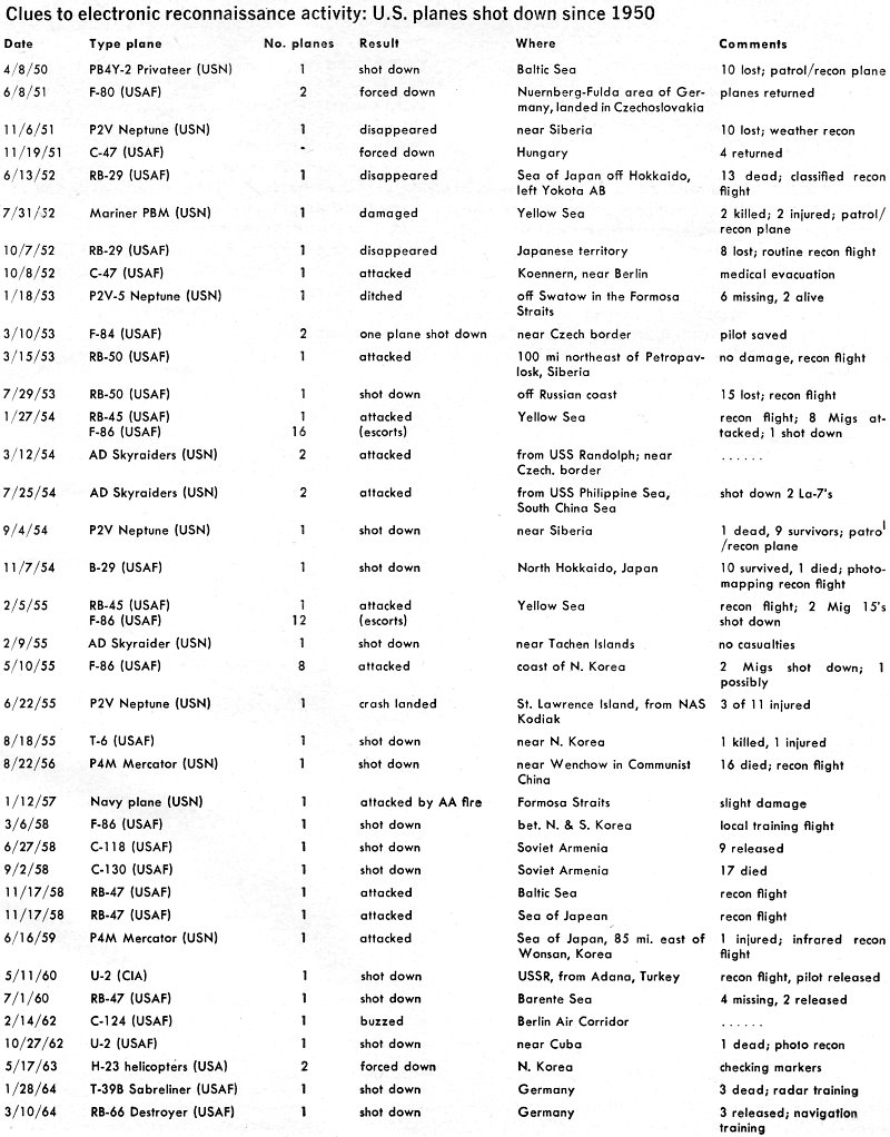
Clues to electronic reconnaissance activity: U.S. planes shot down since 1950
Types of intercept receivers: the wide-open receiver (A), the wide-open frequency-discriminator receiver (B), a tuned-radio-frequency receiver using Yig tuners and a traveling-wave tube (C), and the latest multiple-channel receiver (D). However, the problems of analysis set a limit on how much of this tape could be processed while the information was still meaningful. Nevertheless, the wide-open receiver and videotape recorder proved useful on missions such as the U-2 flights. By adding a broadband traveling-wave tube to a wide-open receiver (B), it may be possible to get 20 to 25 decibels of gain. Frequency discrimination can be achieved by placing a traveling-wave tube amplifier ahead of an APR-9 receiver that is mechanically swept from 1.0 to 10.5 gigacycles. These receivers were designed at Stanford University, and prototypes were built at the Airborne Instruments Laboratory division of Cutler-Hammer, Inc. Production models were made by Collins Radio. Then came the invention of the yttrium iron-garnet (YIG) tuner. Here a polished sphere of yttrium iron garnet is placed inside a magnetic solenoid within a waveguide. Passing current through the solenoid permits varying the frequency of the YIG tuner over an octave bandwidth - roughly 25% above and below center frequency. YIG tuners are available to tune in decade increments from 200 to 18,000 megacycles. Their insertion losses vary from five to eight decibels. A typical microwave tuned radio-frequency receiver using input and output YIG tuners with a wideband traveling-wave tube between them (C) can tune over an octave in frequency at a scanning rate of 100 cycles per second. Such a receiver is useful in working with modern spectrum analyzers. Multiple-Channel Receiver The latest in electronic reconnaissance receivers is the multiple-channel system USD-7, a prototype of which was recently completed (D). It is to be manufactured by the Airborne Instruments Laboratory. The receiver increases the frequency intercept capability of reconnaissance equipment to the Ku band from its present X-band capability. The USD-7 is being miniaturized; it will use only solid-state, and perhaps some microelectronic, components. The receiver covers the entire band of interest using a series of detectors and YIG filters. It can be made to work with an array of directional antennas for direction-finding. A major problem in the development of multiple-channel receivers was interaction between channels. This required an "ambiguity eliminator" to discriminate between desired signals and spurious responses, and design work on YIG filters. Developmental reconnaissance receivers have been built using tunnel diodes, parametric amplifiers and even masers. But the more the sensitivity of a receiver is increased, the more difficult become the problems of shielding the receiving installation. Traveling-wave tubes cannot be swept in frequency, but they do afford an octave or so of bandwidth. Furthermore, it is possible to design a tube to function simultaneously as both an amplifier and mixer. But the tubes do generate spurious signals, and it is hard to make each identical to every other. This is especially bad in direction-finder applications in which two receivers are mounted in pods on opposite wingtips of an aircraft. Also, operation of traveling-wave tubes always involves a trade-off between noise and gain. For example, a tube with a noise figure of three to six decibels will be saturated by a signal five decibels below one milliwatt, while a tube with a noise figure of 8 to 10 decibels will be saturated by a signal as low as 13 decibels below one milliwatt. This means that if you can tolerate the extra noise you can get twice the radar range.
Electronic reconnaissance: state of the art Some engineers believe that the best electronic reconnaissance system may turn out to be an infrared detector that can pick out a hot radar antenna even when the antenna is not transmitting. Of course, use of infrared receivers would require ferrets to work even closer to the transmitter, with all attendant risks. Signal Analysis During World War II, operators used pulse analyzers to determine the characteristics of radar intercepts. These instruments used bucket-capacitor circuits and analog-type panel meters to measure and display pulse width and repetition rate. Latest Ferrets: Electronic Reconnaissance Planes In addition, panoramic intercept adaptors were used to display a frequency spectrum equal to the intercept receiver's intermediate-frequency and centered upon the frequency to which the receiver was tuned. Wire recorders, and later tape, were used to capture signals for later analysis. With the advent of videotape recording it became possible to record signal bandwidths that greatly exceeded the limitation of one kilocycle per inch per second that restricted the range of conventional tape recorders.
Lockheed A-11 is a 2,000-mph aircraft with a service ceiling of 70,000 feet. It is designed to carry a heavy load of electronic and photo-reconnaissance equipment. Its range is reported to exceed 4,000 miles. An example of a tape recorder that could be used in electronic reconnaissance is the Ampex VRX-1006. This single-channel wide-band recorder has a four-megacycle frequency response and can record up to 90 minutes. It uses two-inch tape on either 12 1/2- or 14-inch reels. Its peak time-displacement error is plus or minus 20 nanoseconds and it can begin recording data two seconds after observation begins. Doing It with Pictures After World War II, graphic displays have been found to be more informative than the analog meter presentation. For example, a four-gun cathode-ray oscilloscope triggered by the intercepted pulse (or operating with an astable sweep generator) can provide a display of time vs. amplitude (A). Such a display clearly illustrates the lobe pattern of a radar beam as the beam rotates past the receiving antenna, and is useful in analyzing pulse-time multiplexed signals. The calibrated horizontal sweep ranges of the four guns extend from 0.1 microsecond per centimeter to one second per centimeter. Also, the current waveform applied to the YIG filter of an electronically tuned intercept receiver may be slaved to the horizontal sweep of a cathode-ray oscilloscope to provide a frequency-vs.-amplitude display of the whole frequency band of interest. Such a display is not affected by the receiver intermediate-frequency bandpass characteristics, as is the conventional panoramic adapter display (B).
Analysis equipment: amplitude vs. time display using 4-gun cathode-ray tube (A), spectrum analyzer giving an amplitude vs. frequency display of an octave or more (B), and frequency vs. time display. The excellent bandpass characteristics of modern intercept receivers and spectrum analyzers permit displaying the intermediate frequency of the intercepted signal directly on the scope face of the spectrum analyzer. In this way, unique spectral signatures of individual items of hostile equipment can be obtained and identified. The technique permits following closely the redeployment of electronic material. The operator can even tell when the enemy changes his magnetrons! The outputs of a multiple-channel receiver can be applied to video filters with slightly overlapping response characteristics to provide a time-vs.-frequency display (C): This display can, in turn, be intensity-modulated to add amplitude information. Such a three-dimensional intercept display can be very useful. Graphical intercept outputs are photographed to provide a permanent record for later analysis. A back-printing fiber-optic display device can be employed to continuous annotate the intercept record with positional information derived from the aircraft's latitude-longitude computer. Modern cathode-ray tubes permit simultaneous photography of the scope display and viewing by the intercept operator. Director Finding The final chore of the operator is to get a DF fix on the hostile transmitter. Formerly, two antennas were used for reconnaissance, both housed in a radome beneath the ferret plane. One was a discone for omni-directional reception. The other consisted of two microwave-horn antennas back to back, one polarized vertically, the other horizontally. The antenna rotated in synchronism with a PPI oscilloscope trace to present a twin-leaf pattern pointing at signal maximum. This was unsatisfactory because of the effects of the radome on the aircraft's aerodynamic configuration and because of the time required to get a bearing. Furthermore, the oscilloscope presentation of a signal maximum is never as precisely defined as the visual presentation of a signal minimum or null indication. Modern systems use flush-mounted broadband antennas located in different parts of the plane. Polarity of the receiving antenna system can be switched easily and quickly from horizontal to vertical to circular. Use of log periodic antennas permits covering a 10-to-1 bandwidth while a goniometer presentation provides an instantaneous display fixing on the signal null. The speed of modern ferret aircraft, as well as provisions for automatic positional annotation, permit a lone plane to triangulate hostile stations quickly. Integrated Reconnaissance A trend in ferreting will be an integrated servo system combining aerial photography, electromagnetic reconnaissance, infrared and ultraviolet devices.
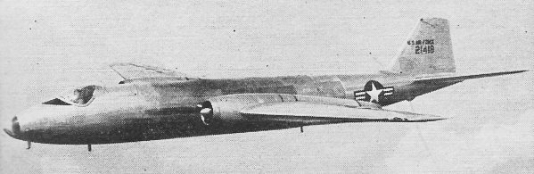
Martin RB-57D Night Intruder is a U. S. Air Force version of the English Electric Canberra. Basic aircraft is a single-place twin jet; the version used in overflights of Red China is a larger airplane.
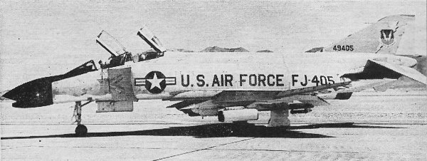
McDonnell RF-4C Phantom II will become a major electronic reconnaissance plane for the Air Force. Its top speed exceeds 1,400 miles an hour. Later on, the Navy will probably go to the Grumman EA-6A Intruder. One such system was the Little Snooper, a Boeing C-45 outfitted with aerial cameras by Chicago Aerial Industries, Inc., electronic reconnaissance gear by Ling-Temco-Vought, Inc., videotape recorders by the Ampex Corp., infrared surveillance equipment by HRB-Singer, Inc., and a General Electric low-light-level television camera. The aircraft flew in May, 1963. And the Future Even if general disarmament were agreed to by the major nations of the world, either the signers of such a treaty or some supernational agency would have to carry on ferreting operations to guard against violations of the treaty. In fact, the U. S. Arms Control and Disarmament Agency is vitally interested in such reconnaissance. Peace can flourish only when nations are secure in the knowledge that no sneak attack is imminent, and electronic reconnaissance can help to grant that assurance. Yet every ferret flight risks not only the lives of the airmen involved but the peace of the world. However, there may be a better way. A day may come when U. S. ferret planes with light blue noses, wing tips and tail surfaces will patrol one side of the East-West border with Russian pilots at the controls and Russian navigators plotting the course, while similarly equipped Bears and Badgers with Americans in command patrol the Eastern side of the frontier. And Irish, Swedish and Burmese operations analysis officers may probe the log-books and scan the magnetic tapes, looking for - but hopefully never finding - evidence of treaty violations. The author thanks John F. Mason, Senior Associate Editor, and Laurence D. Shergalis, Regional Editor, San Francisco, and Herbert Cheshire, McGraw-Hill World News, Washington, for their help in gathering material for this article.
Posted April 2, 2019 |
|
")