Corrugated-Waveguide Band−Pass Filters
|
|
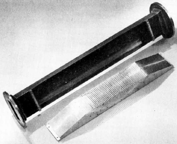
Maybe in 1951 when this "Corrugated-Waveguide Band−Pass Filters" article appeared in Electronics magazine, placing a special resonating form inside a section of waveguide was a reasonable option for creating a bandpass filter response, but it sure seems like a hard way of accomplishing the task. As shown in the photo and illustrations, a tapered metallic block with machined fins spaced to resonate at a predetermined frequency created a high frequency cutoff to work in conjunction with the natural low frequency cutoff frequency to create a bandpass combination. A quick search did not turn up any references to such structures being used in modern waveguide bandpass filters, although they might exist. It appears iris coupling of resonating cavities is the method du jour. I admit to not being a waveguide expert, so do your own research on this one. If nothing else, this is a good historical reference. High−pass properties of a waveguide are combined with low−pass properties of a corrugated surface in a filter designed to give a rapid transition between pass and attenuation bands. Single corrugated element does work of several elements in conventional designs
Section of waveguide and corrugated surface which fits into it. By J. C. Greene, Rapid transition between pass and attenuation bands and a wide frequency range free of spurious responses are desirable properties of a band−pass filter. Such a filter can be realized readily by combining the high-pass properties of a waveguide with the low−pass property of a corrugated surface. In a particular application a filter was designed which had a passband between 2,080 mc and 2,800 me and 70−db attenuation, relative to the pass−band response, at 2,900 mc. There were no responses which were not attenuated by at least 60 db from 2,900 me to above 10,000 mc. Because of the high−pass characteristic of a waveguide, a band−pass filter can be formed readily by incorporating a low−pass structure into the waveguide. One such lowpass structure is the corrugated surface for which approximate field solutions have been given in the literature1-6. The design considered in this paper for utilizing the corrugated surface structure is shown in Fig. 1, where one broad face of the waveguide is replaced by a tapered corrugated surface. Approximate solutions for the attenuation and phase characteristics of the filter in Fig. 1 are obtained by combining design relations with a loaded−line equivalent circuit representation1.
Fig. 1 - Mechanical drawing of tapered corrugated surface which replaces one face of the waveguide.
Fig. 2 - Idealized pass−band shape. High-frequency attenuation at t = ∞ is provided by resonance of the slots in region C of corrugated surface (see Fig. 1).
Fig. 3 - Loaded transmission line representation of one slot in the corrugated surface.
Fig. 4 - Theoretical curves relating attenuation in db per section and phase shift across one slot for transmission line of length 1' (see Fig. 1) to the phase shift along the distance between two slots.
Fig. 5 - Attenuation curve for actual filter constructed. An idealized pass−band shape is illustrated in Fig. 2. The low-frequency cutoff f, is provided by the normal cutoff of the waveguide, while the high−frequency cutoff f ∞, at which there is infinite attenuation, is provided by a resonance of the slots in region C of the corrugated surface. The slots in region B of the corrugated surface serve a twofold purpose. They provide additional resonant elements in the upper rejection band (f > f ∞) to prevent repetitive pass bands. In addition they serve as a smooth taper which transforms the characteristic impedance of region C into the characteristic impedance of the waveguide through the taper in region A. Filter Characteristics The loaded transmission-line representation of one slot in the corrugated surface is shown in Fig. 3. The characteristic equation of the frequency spectrum relating the phase shift Φ, across one element of the loaded line (including both the slot and the transmission line of length l' to the phase shift Θ along l' between two adjacent slots is
where a is the broad dimension of the waveguide. Putting Φ = ß - jα and neglecting resistive losses one obtains for the pass band (α = 0) cos (ß + 2 n π) = cos θ - (Z/2Z0) sin θ tan (pθ) (3) where n = 0, ±1, ±2, etc. and in the cutoff band (ß = 0 or π) ± cosh α = cos θ - (Z/2Z,) sin (θ) tan (pθ) where α = attenuation in nepers per section of loaded line, (ß + 2nπ) = phase shift per section of loaded line. The values of n0 in Eq. 3 represent space harmonics of the fundamental (n = 0) component of the wave. The positive values of n represent transmitted waves, the negative values reflected waves. All of these components are necessary to fully describe the propagated wave. To simplify the analysis, the space harmonic components are neglected. This is a valid assumption in the pass band, since the amplitudes of the space harmonics are greatly reduced in the pass band. The assumption becomes less valid as the frequency approaches that at which the slots become resonant. Design relationships among the dimensions of a slot are5 b'/2 < l' < (λg1)2/10 (5) b'/b < 0.1 (6) where λg1 is the guide wavelength in the unloaded section at the upper cutoff frequency, f1. It can be demonstrated that the pass−band resistive losses due to a finite conductivity in the conducting surfaces vary inversely with the quantity b'/b. This value was chosen to be as large as possible, namely 0.1. It may be seen from Eq. 4 that an infinite attenuation occurs when pθ = π/2. The frequency at which this infinite attenuation occurs is f∞. However,
Hence at the infinite attenuation frequency (λg = λg∞) or
Eq. 7 means that at the infinite attenuation frequency, the slot depth, (b - b') /2, equals one quarter of a guide wavelength. The values of l and l' are not critical and are generally chosen to keep the over−all length of the filter as short as possible. Typical values are l' = 2l = 0.1co∞. The value of the ratio Z/Z0 is taken to be 2l/b', the ratio of the slot height to the line height. Theoretical curves relating 4, and a in db to e are shown in Fig. 4. The curves have been calculated for p = 2 and Z/Z0 = 2. At the point of infinite attenuation, θ = 45 deg, while at the upper cutoff point θ = 36 deg. Hence the ratio of the cutoff wavelength, λg1 to the infinite attenuation wavelength, λg∞ is λg1/λg∞ = 45 deg/36 deg = 1.25. The slot requires the cutoff wavelength to be decreased by 25 percent before its attenuation becomes infinite. Referring to Fig. 4, representing the characteristics of the slots in region C of the filter, it can be seen that repetitive pass bands will occur. The first repetitive pass band occurs when λg = λg1/2. To avoid this pass band as well as higher ones, it is necessary to include slots in region B of the filter which will resonate in the vicinity of the higher passbands. In general, this condition is fulfilled merely by having a reasonable length of taper. Design Procedure The filter can be easily incorporated as an inserted section in a waveguide, with waveguide input and output. It can also be incorporated into a coaxial line through the use of waveguide to coaxial transformers. The transforming sections form the input and output of the filter. The low-frequency cutoff determines the wide dimension of the waveguide, a, and is simply related to it by λc= 2a Generally, both the upper cutoff frequency f1 and a minimum attenuation at a point between f1 and f∞ are specified. Once these are known, the slot depth and number of slots in region C can be determined. First a is calculated from the high−frequency cutoff f, by Eq. 2. Because λg1/ λg∞ = 1.25, λg∞ may be readily found. The slot depth is then made equal to λg∞/4. The number of slots required is the desired attenuation in db at some frequency between f1 and f∞ divided by the attenuation of one slot at that frequency as determined from Fig. 4. The lengths of the tapered sections in regions A and B should be about equal and as long as possible for the best match. A theoretical curve relating the vswr introduced by a taper as a function of its length has been given by Frank'. From this curve and a consideration of the variation in guide wavelength in the pass band, a value giving small mismatch reflections over the entire pass band is found to be 1.5 λc or 3a. Experimental Results An experimental curve for the filter based on the previous design considerations is given in Fig. 5. The corrugated surface was designed to be inserted in standard 1.5 by 3−in. waveguide having a cutoff frequency of 2,080 mc. The desired upper cutoff frequency was 2,800 mc (λg1 = 16.0 cm.) This gives the infinite attenuation frequency as 3,200 mc (λg∞ = 12.8 cm). It was also desired to have at least 70 db of attenuation at 2,900 mc (λg = 15.0 cm). Because λg1 corresponds to θ = 36 deg. on the curve of Fig. 4, at λg = 15.0 cm, θ = 38.4 deg. From Fig. 4, the attenuation in db per slot at θ = 38.4 deg is 9 db. Hence eight slots in region C should be sufficient to give the desired attenuation. Actually ten slots were used because the attenuation of a slot will be slightly less than shown in Fig. 4 due to resistive losses in the slot. The pass−band loss, averaging approximately 2.5 db, is a combination of resistive loss in the slots and mismatch loss in the tapers. Higher Order Modes In the above analysis it was assumed that only the dominant mode TE1,0 is propagated. For the usual waveguide dimensions (broad face twice as wide as the narrow face) higher−order modes may be propagated at frequencies greater than twice the normal cutoff frequency. If these higher-order modes are propagated, spurious responses may appear in the rejection band. Because of the symmetry of the filter, only TE1,2n (n = 0,1,2, ...) and TM1,2n (n = 1,2,3, ...) modes can be excited within the filter itself4. The first of these modes, the TE1,2 and the TM1,2 will not be propagated for frequencies less than four times the normal cutoff frequency. In general this is far enough into the rejection band to be of little consequence. Should higher−order modes, such as the TE2,0, TE3,0 be set up in the input section leading to the filter, they will pass through the filter and produce narrow spurious pass bands for frequencies in the vicinity of twice the normal cutoff frequency, three times this frequency, and so on. At the cutoff frequency for the higher modes, the guide wavelength for these modes is infinite and rapidly decreases as the frequency is increased. Until the wavelength decreases to a value such that the slots in region C become resonant, no attenuation is offered to the modes. The higher modes can often be eliminated by careful design of the input circuit to eliminate asymmetrical structures tending to excite the higher-order modes. They may also be eliminated in the output section when of a special type, such as ridged waveguide output. In this case, the ridged section is designed so that it passes the dominant mode, but is cut off for the higher−order modes in the vicinity of the spurious response pass bands. Compensating sections of different widths, a, can be included in the filter proper so that they are below cutoff for the higher-order modes over the frequency range of the spurious responses'. References (1) A. W. Lines, G. R. Nicoll and A. M. Woodward, Some Properties of Corrugated Waveguides, Telecommunications Research Establishment Report No. T2114 ; reprinted in Proc. IEE, 97, Part III, No. 48, July 1950. (2) C. C. Cutler, Electromagnetic Waves Guided by Corrugated Conducting Surfaces, Bell Telephone Laboratories Report No. MM44-160-218. (3) H. H. Goldstein, The Theory of Corrugated Transmission Lines and Waveguides, Rad. Lab. Report No. 494, April 1944. (4) S. B. Cohn, Analysis of a Wide- Band Waveguide Filter, Proc. IRE, 37, p 651, June 1949. (5) S. B. Cohn, Design Relations for the Wide-Band Waveguide Filter, Proc. IRE, 38, p 799, July 1950. (6) W. Rotman, A Study of Single Surface Corrugated Guides, Air Force Cambridge Research Laboratory Report No. E5055, Feb. 1950. (7) N. H. Frank, Dielectric Structures in Waveguides, "Rad. Lab. Handbook," p 30, Feb. 1943. (8) Radio Research Laboratory Staff, "Very-High-Frequency Techniques," Mc- Graw-Hill Book Co., New York, Section 27-28, 1947.
Posted March 20, 2024 |
|
")