Electricity - Basic Navy Training Courses
|
|
Here is the "Electricity - Basic Navy Training Courses" (NAVPERS 10622) in its entirety. It should provide one of the Internet's best resources for people seeking a basic electricity course - complete with examples worked out. See copyright. See Table of Contents.
¶ U.S. GOVERNMENT PRINTING OFFICE; 1945 - 618779
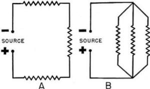
CHAPTER 9 Parallel circuits are MULTIPLE circuits - they have MORE THAN ONE PATH between the two terminals of the source. Compare the two circuits in figure 47. In both cases the current is forced by a potential to flow from - to +. In the series circuit, the current travels along only ONE path. But in the parallel circuit the current divides and, in this case, travels along THREE paths. In the series circuit only ONE conductor is connected to each terminal. But, in the parallel circuit, MORE THAN ONE conductor may be connected to a terminal. Imagine that you are laying out a road system between town A and town B. You have the choice of two systems. 1. One road directly between the two towns. 2. A network of several roads running parallel to each other between the two towns. The first type is like the series circuit and the second is like the parallel circuit.
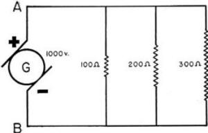
Figure 47. - Series and parallel compared. VOLTAGE IN PARALLEL CIRCUITS Carry the comparison a little farther - consider town A to be on top of a 1,000 foot hill and town B to be in the valley below. In order to go from A to B you must drop 1,000 feet. In the series system, the ONE road drops this 1,000 feet. In the parallel system EVERY road drops 1,000 feet. The same problem in a parallel electrical system is illustrated in figure 48.
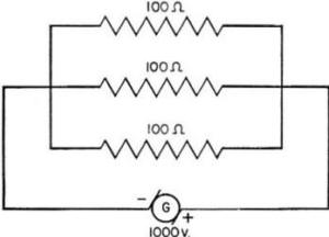
Figure 48. - Voltage in a parallel circuit. There is a potential difference of 1,000 volts across every path between A and B. In the electrical system A and B are the terminals of the generator. No matter which path (branch) you take from A to B-the voltage force on the current is 1,000 volts. This gives you the law for voltage in a parallel circuit - THE VOLTAGE IS THE SAME ACROSS ALL BRANCHES OF A PARALLEL CIRCUIT. Or mathematically - Et = E1 = E2= E3, etc. When - Et = total or source voltage; E1 = voltage drop through first load; E2 = voltage drop through second load; E3 = voltage drop through third load. Compare the 100 ohm load to the 200 ohm load in figure 48. Note that these loads have different resistances but their voltages are the SAME. This is similar to the problem of the two roads from town A to town B. One road may be narrow and rough - its resistance is high. The other may be broad and smooth - its resistance is low. But BOTH roads, regardless of resistance, drop 1,000 feet. CURRENT IN PARALLEL CIRCUITS Assuming equal quality of road construction, which system would carry the greatest traffic from town A to town B, the one-road series, or the net-work-parallel? The parallel, of course, because it has more paths (roads). Say each road can carry 10 cars per minute. Then the one-road series system carries just ten cars per minute. But the three-road parallel system carries 30 cars per minute. Figure 49 shows a 3-branch parallel with equal loads of 100 ohms resistance. The generator voltage is 1,000 volts. The current in each branch can be calculated by OHM'S law - I1 = E1/R1 = 1,000/100 = 10 amps. Since the voltage and resistance are the same for the other branches, their current is 10 amperes also. Now, since each load draws 10 amperes from the generator, the total current is - 10 + 10 + 10 = 30 amps.
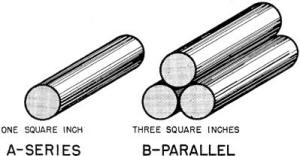
Figure 49.-Current in a parallel circuit. This gives you the law for current in a parallel circuit - THE TOTAL CURRENT IN A PARALLEL CIRCUIT IS THE SUM OF THE CURRENTS OF ALL THE BRANCHES. Or mathematically - It = I1 + I2 + I3, etc. When - It = the total current; I1 = the current through the first load; I2= the current through the second load; I3 = the current through the third load. RESISTANCE IN PARALLEL CIRCUITS Referring back to figure 49, notice that the current path from - to + is over the three wires. View A of figure 50 shows only one of these conductors cut to show a cross-section. Say that this conductor is one square inch in a cross-sectional area. The current flowing through this ONE wire is very much like water flowing through ONE pipe. But if you combine the THREE wires, you would have a cross section like B in figure 50. This combination has three square inches instead of one square inch of cross-sectional area. Now the current flowing through the THREE wires, is very much like water flowing through three pipes. It is just three times as easy to force the same current through the 3-wire parallel as it is through a one-wire series (same size of wire). If it is three times as easy - the resistance is one-third as much.
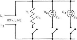
Figure 50. - Resistance in a parallel circuit. What was that? The resistance is less when there are more wires? Exactly - because the MORE BRANCHES you add to a parallel circuit, the EASIER it becomes to force current from - to +. This gives you a general idea of resistances in parallel - THE MORE LOADS ADDED IN PARALLEL, THE LESS THE TOTAL RESISTANCE. To get the actual law of resistances in parallel, you must derive it mathematically. (1) You know that It = I1 + I2 + I3; and you know that It = Et/Rt; I1 = E1/R1; I2 = E2/R2; I3 = E3/R3 (2) If in the formula It = I1 + I2 + I3, the E/R values are substituted for all values of I, it becomes - Et/Rt = E1/R1 + E2/R2 + E3/R3 (3) Now, since the parallel circuits, Et = E1 = E2 = E3, you can substitute Et for all values of E - Et/Rt = Et/R1 + Et/R2 + Et/R3 (4) and dividing each member of the equation by Et - 1/Rt = 1/R1 + 1/R2 + 1/R3, etc. When - Rt = the total resistance; R1 = the resistance of the first load; R2 = the resistance of the second load; R3 = the resistance of the third load. Or: stated in words - IN PARALLEL CIRCUITS, THE RECIPROCAL OF THE TOTAL RESISTANCE EQUALS THE SUM OF THE RECIPROCALS OF THE RESISTANCES OF ALL BRANCHES. Using the problem in figure 49, what is the total resistance of the circuit? 1/Rt = 1/R1 + 1/R2 + 1/R3 1/Rt = 1/100 + 1/100 + 1/100 1/Rt = 3/100 Rt = 100/3 = 33.33 ohms. This proves that three equal resistors, in parallel, have a TOTAL resistance of only one-third the resistance of EACH resistor. Ohm's law provides an easier method of calculating the total resistance of a parallel circuit. Remember, you use the TOTAL values of the circuit when solving for the TOTAL values. Rt = Et/It = 1000/30 = 33.33 ohms. PROBLEMS IN PARALLEL CIRCUITS The parallel circuit is used for INDEPENDENT loads - that is, loads which are NOT controlled by other loads. Most electrical loads are of this type. You certainly would want the ship's running lights to be independent of the cook's galley. And it is definitely good sense to have the bilge pump motors independent of the steering motors! The circuits which follow are typical parallel circuits. When you study them, remember the six rules in Chapter 8 for solving problems - these rules apply equally well to parallel circuits. EXAMPLE 1 - Two lamps and a heater are connected in parallel across a 110-volt line. Each load is controlled by a separate switch and draws the current indicated in figure 51. Calculate the resistance of each load and the total resistance.
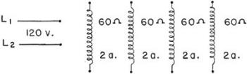
Figure 51. - Example 1 For first load: R1 = E1/I1 = 110/10 = 11 ohms. For first load: R2 = E2/I2 = 110/2 = 55 ohms. For first load: R3 = E3/I3 = 110/2 = 55 ohms. For first load: Rt = Et/It = 110/14= 7.86 ohms. There is also the reciprocal method of calculating the TOTAL resistance - 1/Rt = 1/R1 + 1/R2 + 1/R3 1/Rt = 1/11 + 1/55 + 1/55 1/Rt = 5/55 + 1/55 + 1/55 1/Rt = 7/55 Rt = 55/7 = 7.86 ohms. You will notice that the reciprocal method is much tougher - use OHM'S LAW for TOTAL resistance whenever possible. It was required that each load be separately Controlled. In order to control a load, the SWITCH is in SERIES with that particular load, but the LOADS are in PARALLEL with each other. Thus, opening the HEATER SWITCH opens the HEATER CIRCUIT, but does NOT turn off the lights. The same is true of the light switches - they control ONLY the load with which they are in series. EXAMPLE 2 - A motor has four coils. The resistance of each coil is 60 ohms, and each coil must be connected to receive 2 amperes of current. (1) How would you connect these coils in a 120-v. line? (2) What is the total current drawn from the line? (3) What is the total resistance of your connections? (4) How much power is consumed in each coil? In all the coils?
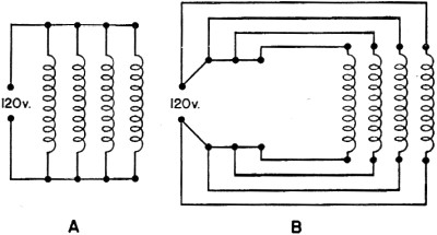
Figure 52. - Example 2 (1) You would first draw your circuit as in figure 52. Then calculate the voltage required to force 2 amperes through 60 ohms of resistance. E1 = I1R1 = 2 x 60 = 120 v. Since each coil needs 120 volts, they will have to be paralleled to get the full line voltage. You would now complete your diagram by making this connection. Remember, in order to be in parallel, each coil will have to be connected DIRECTLY to the line. Figure 53 shows two ways you might complete your diagram. Both are correct. In this case, A, is the better method, because it uses less wire.
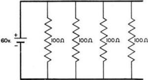
Figure 53. - Connections for Example 2. (2) It = I1 + I2 + I3, etc. It = 2 + 2 + 2 + 2 = 8 amps. (3) Rt = Et/It = 120/8 = 15 ohms. (OR 1/Rt = 1/60 + 1/60 + 1/60 + 1/60 = 4/60 1/Rt = 4/60 Rt = 60/4 - 15 ohm.) (4) P1 = E1I1 P1 = 120 x 2 = 240 watts - for each coil Pt = EtIt (RF Cafe note: original had P1 = EtIt) Pt = 120 x 8 = 960 watts - total. (RF Cafe note: original had P1 = 120 x 8) EXAMPLE 3 - Figure 54 shows a resistance bank of four resistors. These resistors are connected in parallel to permit the maximum current to pass. If each resistor has 100 ohms resistance, what is the current passed from the 60-volt battery? How much current does each resistor carry? 1/Rt = 1/R1 + 1/R2 + 1/R3, etc. 1/Rt = 1/100 + 1/100 + 1/100 + 1/100 1/Rt = 4/100 Rt = 100/4 = 25 ohms. It = Et/Rt = 60/25 = 2.4 amps, from the battery It = Et/Rt = 60/100 = 0.6 amps, from the battery Because the resistance in each resistor is the same, the current is the same. Thus - I1 = 12 = I3 = I4 = 0.6 amp for each resistor.
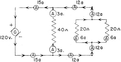
Figure 54. - Example 3 EXAMPLE 4 - To be sure that you understand the current paths in a parallel circuit, the example in figure 55 has ammeters and arrows in all lines. The ammeters read the current flowing, and the arrows show the direction. Trace this circuit through carefully. If you understand each reading, you can account for all the current flowing. And by using Ohm's law, you can prove that all the EMF of the generator is used up in the circuit.
Figure 55. - Example 4
Chapter 9 Quiz
|