Module 3 - Introduction to Circuit Protection, Control, and Measurement
|
||||||||||||||||||||||||||||||||||||||||||||||||||
|
Rectifier for AC Measurement
Module 3 −− Introduction to Circuit Protection, Control, and Measurement
Pages i, 1−1, 1−11, 1−21, 1−31, 1−41, 1−51, 1−61, 1−71, 2−1, 2−11, 1−21, 2−31, 2−41, 3−1, 3−11, 3−21, 3−31, AI−1, AII−1, AIII−1, IV−1, Index
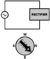
Figure 1-12. - Rectifier action. A rectifier is a device that changes alternating current to a form of direct current. The way in which this is done will be covered later in this training series. For now, it is necessary to know only the information presented in figure 1-12. Figure 1-12 shows that an alternating current passed through a rectifier will come out as a "pulsating direct current."
Figure 1-13. - Compass and conductor; rectified AC. What happens to the compass now? Figure 1-13 answers that question. When the compass is placed close to the wire and the frequency of the alternating current is high enough, the compass will vibrate around a point that represents the average value of the pulsating direct current, as shown in figure 1-13. Q10. How would a compass react when placed close to a conductor carrying alternating current at a low frequency? Q11. How would the compass react if the alternating current through the conductor was a high frequency? Q12. What is the purpose of a rectifier in a meter? By connecting a rectifier to a d'Arsonval meter movement, an alternating current measuring device is created. When ac is converted to pulsating dc, the d'Arsonval movement will react to the average value of the pulsating dc (which is the average value of one-half of the sine wave). Another characteristic of using a rectifier concerns the fact that the d'Arsonval meter movement is capable of indicating current in only one direction. If the d'Arsonval meter movement were used to indicate alternating current without a rectifier, or direct current of the wrong polarity, the movement would be severely damaged. The pulsating dc is current in a single direction, and so the d'Arsonval meter movement can be used as long as proper polarity is observed. Damping A problem that is created by the use of a rectifier and d'Arsonval meter movement is that the pointer will vibrate (oscillate) around the average value indication. This oscillation will make the meter difficult to read. The process of "smoothing out" the oscillation of the pointer is known as DAMPING. There are two basic techniques used to damp the pointer of a d'Arsonval meter movement. The first method of damping comes from the d'Arsonval meter movement itself. In the d'Arsonval meter movement, current through the coil causes the coil to move in the magnetic field of the permanent magnet. This movement of the coil (conductor) through a magnetic field causes a current to be induced in the coil opposite to the current that caused the movement of the coil. This induced current will act to damp oscillations. In addition to this method of damping, which comes from the movement itself, most meters use a second method of damping.
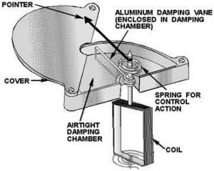
Figure 1-14. - a typical meter damping system. The second method of damping used in most meter movements is an airtight chamber containing a vane (like a windmill vane) attached to the coil (fig.1-14). As the coil moves, the vane moves within the airtight chamber. The action of the vane against the air in the chamber opposes the coil movement and damps the oscillations. Q13. How can a d'Arsonval meter movement be adapted for use as an ac meter? Q14. What is damping? Q15. What are two methods used to damp a meter movement? Q16. What value does a meter movement react to (actually measure) when measuring ac? Q17. What value is indicated on the scale of an ac meter? An additional advantage of damping a meter movement is that the damping systems will act to slow down the coil and help keep the pointer from overshooting its rest position when the current through the meter is removed. Indicating Alternating Current Another problem encountered in measuring ac is that the meter movement reacts to the average value of the ac. The value used when working with ac is the effective value (rms value). Therefore, a different scale is used on an ac meter. The scale is marked with the effective value, even though it is the average value to which the meter is reacting. That is why an ac meter will give an incorrect reading if used to measure dc. Other Meter Movements The d'Arsonval meter movement (permanent-magnet moving-coil) is only one type of meter movement. Other types of meter movements can be used for either ac or dc measurement without the use of a rectifier. When galvanometers were mentioned earlier in this topic, it was stated that they could be either electromagnetic or electrodynamic. Electrodynamic meter movements will be discussed at this point. Electrodynamic Meter Movement
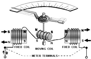
Figure 1-15. - Electrodynamic meter movement. An electrodynamic movement uses the same basic operating principle as the basic moving-coil meter movement, except that the permanent magnet is replaced by fixed coils (fig. 1-15). a moving coil, to which the meter pointer is attached, is suspended between two field coils and connected in series with these coils. The three coils (two field coils and the moving coil) are connected in series across the meter terminals so that the same current flows through each. Current flow in either direction through the three coils causes a magnetic field to exist between the field coils. The current in the moving coil causes it to act as a magnet and exert a turning force against a spring. If the current is reversed, the field polarity and the polarity of the moving coil reverse at the same time, and the turning force continues in the original direction. Since reversing the current direction does not reverse the turning force, this type of meter can be used to measure both ac and dc if the scale is changed. While some voltmeters and ammeters use the electrodynamic principle of operation, the most important application is in the wattmeter. The wattmeter, along with the voltmeter and the ammeter, will be discussed later in this topic. MOVING-VANE METER MOVEMENTS The moving-vane meter movement (sometimes called the moving-iron movement) is the most commonly used movement for ac meters. The moving-vane meter operates on the principle of magnetic repulsion between like poles (fig.1-16). The current to be measured flows through a coil, producing a magnetic field which is proportional to the strength of the current. Suspended in this field are two iron vanes. One is in a fixed position, the other, attached to the meter pointer, is movable. The magnetic field magnetizes these iron vanes with the same polarity regardless of the direction of current flow in the coil. Since like poles repel, the movable vane pulls away from the fixed vane, moving the meter pointer. This motion exerts a turning force against the spring. The distance the vane will move against the force of the spring depends on the strength of the magnetic field, which in turn depends on the coil current.
Figure 1-16. - Moving-vane meter movement.
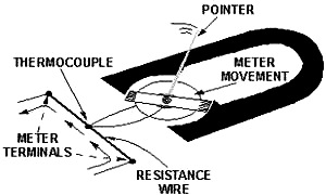
Figure 1-17. - Hot-wire meter movement. Figure 1-18. - a thermocouple meter. These meters are generally used at 60-hertz ac, but may be used at other ac frequencies. By changing the meter scale to indicate dc values rather than ac rms values, moving-vane meters will measure dc current and dc voltage. This is not recommended due to the residual magnetism left in the vanes, which will result in an error in the instrument. One of the major disadvantages of this type of meter movement occurs due to the high reluctance of the magnetic circuit. This causes the meter to require much more power than the D'Arsonval meter to produce a full scale deflection, thereby reducing the meters sensitivity. HOT-Wire and THERMOCOUPLE METER MOVEMENTS Hot-wire and thermocouple meter movements both use the heating effect of current flowing through a resistance to cause meter deflection. Each uses this effect in a different manner. Since their operation depends only on the heating effect of current flow, they may be used to measure both direct current and alternating current of any frequency on a single scale. The hot-wire meter movement deflection depends on the expansion of a high-resistance wire caused by the heating effect of the wire itself as current flows through it. (See fig. 1-17.) a resistance wire is stretched taut between the two meter terminals, with a thread attached at a right angle to the center of the wire. a spring connected to the opposite end of the thread exerts a constant tension on the resistance wire. Current flow heats the wire, causing it to expand. This motion is transferred to the meter pointer through the thread and a pivot. The thermocouple meter consists of a resistance wire across the meter terminals, which heats in proportion to the amount of current. (See fig. 1-18.) Attached to this wire is a small thermocouple junction of two unlike metal wires, which connect across a very sensitive dc meter movement (usually a d'Arsonval meter movement). As the current being measured heats the heating resistor, a small current (through the thermocouple wires and the meter movement) is generated by the thermocouple junction. The current being measured flows through only the resistance wire, not through the meter movement itself. The pointer turns in proportion to the amount of heat generated by the resistance wire. Q18. List three meter movements that can measure either ac or dc without the use of a rectifier. Q19. What electrical property is used by all the meter movements discussed so far? Ammeters An ammeter is a device that measures current. Since all meter movements have resistance, a resistor will be used to represent a meter in the following explanations. Direct current circuits will be used for simplicity of explanation. Ammeter Connected in Series
Figure 1-19. - a series and a parallel circuit. In figure 1-19(A), R1 and R2 are in series. The total circuit resistance is R2 + R2 and total circuit current flows through both resistors. In figure 1-19(B), R1 and R2 are in parallel. The total circuit resistance is
and total circuit current does not flow through either resistor. If R1 represents an ammeter, the only way in which total circuit current will flow through the meter (and thus be measured) is to have the meter (R1) in series with the circuit load (R2), as shown in figure 1-19(A). In complex electrical circuits, you are not always concerned with total circuit current. You may be interested in the current through a particular component or group of components. In any case, an ammeter is always connected in series with the circuit you wish to test. Figure 1-20 shows various circuit arrangements with the ammeter(s) properly connected for measuring current in various portions of the circuit. Connecting an ammeter in parallel would give you not only an incorrect measurement, it would also damage the ammeter, because too much current would pass through the meter.
Figure 1-20. - Proper ammeter connections
Figure 1-21. - Current in a parallel circuit. Effect on Circuit Being Measured The meter affects the circuit resistance and the circuit current. If R1 is removed from the circuit in figure 1-19(A), the total circuit resistance is R2. Circuit current with the meter (R1) in the circuit, circuit resistance is R1 + R2 and circuit current The smaller the resistance of the meter (R1 ), the less it will affect the circuit being measured. (R1 represents the total resistance of the meter; not just the resistance of the meter movement.) Ammeter Sensitivity Ammeter sensitivity is the amount of current necessary to cause full scale deflection (maximum reading) of the ammeter. The smaller the amount of current, the more "sensitive" the ammeter. For example, an ammeter with a maximum current reading of 1 milliampere would have a sensitivity of 1 milliampere, and be more sensitive than an ammeter with a maximum reading of 1 ampere and a sensitivity of 1 ampere. Sensitivity can be given for a meter movement, but the term "ammeter sensitivity" usually refers to the entire ammeter and not just the meter movement. An ammeter consists of more than just the meter movement. AMMETER RANGES If you have a meter movement with a sensitivity of 1 milliampere, you can connect it in series with a circuit and measure currents up to 1 milliampere. But what do you do to measure currents over 1 milliampere?
In figure 1-21(B), the voltage is increased to 100 volts. Now,
In figure 1-21(C), the voltage is reduced from 100 volts to 50 volts. In this case,
Notice that the relationship (ratio) of IR1 and IR2 remains the same. IR2 is nine times greater than IR1 and IR1 has one-tenth of the total current. If R1 is replaced by a meter movement that has 10 ohms of resistance and a sensitivity of 10 amperes, the reading of the meter will represent one-tenth of the current in the circuit and R 2 will carry nine-tenths of the current. R2 is a Shunt resistor because it diverts, or shunts, a portion of the current from the meter movement (R1). By this method, a 10-ampere meter movement will measure current up to 100 amperes. By adding a second scale to the face of the meter, the current can be read directly. By adding several shunt resistors in the meter case, with a switch to select the desired resistor, the ammeter will be capable of measuring several different maximum current readings or ranges. Most meter movements in use today have sensitivities of from 5 microamperes to 1 milliampere. Figure 1-22 shows the circuit of meter switched to higher ranges, the shunt an ammeter that uses a meter movement with a sensitivity of 100 microamperes and shunt resistors. This ammeter has five ranges (100 microamperes; 1, 10, and 100 milliamperes; 1 ampere) selected by a switch.
Posted July 25, 2021 |
||||||||||||||||||||||||||||||||||||||||||||||||||