Module 1 - Introduction to Matter, Energy, and Direct Current |
||||||||||||||||||||||||||||||||||||||||||||||||||
|
Module 1 − Introduction to Matter, Energy, and Direct Current
Pages i, 1−1, 1−11, 1−21, 1−31, 1−41, 1−51, 1−61, 2−1, 2−11, 2−21, 3−1, 3−11, 3−21, 3−31, 3−41, 3−51, 3−61, 3−71, 3−81, 3−91, 3−101, 3−111, 3−121, Appendix I, II, III, IV, V, Index
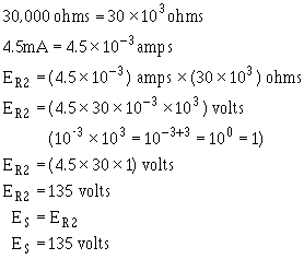
Since the source voltage is equal to the voltage a branch:
To simplify the math operation, the values can be expressed in powers ten as follows:
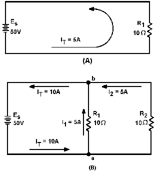
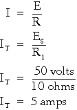
If you are not familiar with the use the powers 10 or would like to brush up on it, Mathematics, Vol. 1, NAVEDTRA 10069-C, will be great help to you. Q33. What would the source voltage (ES) in figure 3-39 be if the current through R2 were 2 milliamps? Current in a Parallel Circuit Ohm's law states that the current in a circuit is inversely proportional to the circuit resistance. This fact is true in both series and parallel circuits. There is a single path for current in a series circuit. The amount current is determined by the total resistance the circuit and the applied voltage. In a parallel circuit the source current divides among the available paths. The behavior current in parallel circuits will be shown by a series illustrations using example circuits with different values resistance for a given value applied voltage. Part (A) figure 3-40 shows a basic series circuit. Here, the total current must pass through the single resistor. The amount current can be determined.
3-51
Figure 3-40. - Analysis current in parallel circuit. Given:
Solution:
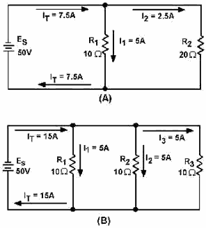
Part (B) figure 3-40 shows the same resistor (R1) with a second resistor (R2) equal value connected in parallel across the voltage source. When Ohm's law is applied, the current flow through each resistor is found to be the same as the current through the single resistor in part (A).
3-52 Given:
Solution:
It is apparent that if there is 5 amperes current through each the two resistors, there must be a TOTAL CURRENT 10 amperes drawn from the source. The total current 10 amperes, as illustrated in figure 3-40(B), leaves the negative terminal the battery and flows to point a. Since point a is a connecting point for the two resistors, it is called a JUNCTION. At junction a, the total current divides into two currents 5 amperes each. These two currents flow through their respective resistors and rejoin at junction b. The total current then flows from junction b back to the positive terminal the source. The source supplies a total current 10 amperes and each the two equal resistors carries one-half the total current. Each individual current path in the circuit figure 3-40(B) is referred to as a BRANCH. Each branch carries a current that is a portion the total current. Two or more branches form a Network. From the previous explanation, the characteristics current in a parallel circuit can be expressed in terms the following general equation:
IT = I1 + I 2 + . . . In
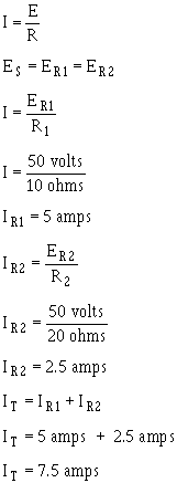
3-53 Compare part (A) figure 3-41 with part (B) the circuit in figure 3-40. Notice that doubling the value the second branch resistor (R2) has no effect on the current in the first branch (IR1), but does reduce the second branch current (IR2) to one-half its original value. The total circuit current drops to a value equal to the sum the branch currents. These facts are verified by the following equations. Given:
Solution:
3-54
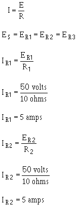
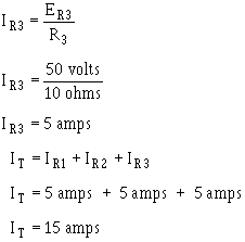
Figure 3-41. - Current behavior in parallel circuits. The amount current flow in the branch circuits and the total current in the circuit shown in figure 3-41(B) are determined by the following computations. Given:
3-55 Solution:
Notice that the sum the ohmic values in each circuit shown in figure 3-41 is equal (30 ohms), and that the applied voltage is the same (50 volts). However, the total current in 3-41(B) (15 amps) is twice the amount in 3-41(A) (7.5 amps). It is apparent, therefore, that the manner in which resistors are connected in a circuit, as well as their actual ohmic values, affect the total current. The division current in a parallel network follows a definite pattern. This pattern is described by Kirchhoff's CURRENT LAW which states:
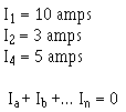
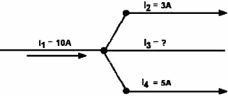
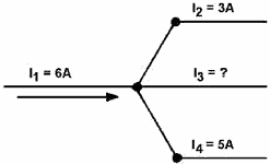
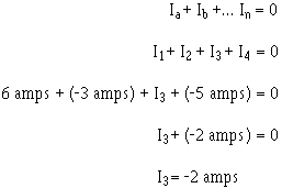
3-56 "The algebraic sum the currents entering and leaving any junction conductors is equal to zero." This law can be stated mathematically as: Ia + Ib + . . . I n + O where: Ia, Ib, etc., are the currents entering and leaving the junction. Currents ENTERING the junction are considered to be Positive and currents LEAVING the junction are considered to be Negative. When solving a problem using Kirchhoff's current law, the currents must be placed into the equation WITH The PROPER POLARITY SIGNS ATTACHED. Example: Solve for the value I3 in figure 3-42. Given:
Solution: Ia + lb + . . . I a + O Figure 3-42. - Circuit for example problem. The currents are placed into the equation with the proper signs.
3-57
13 has a value 2 amperes, and the negative sign shows it to be a current LEAV1NG the junction. Example. Using figure 3-43, solve for the magnitude and direction 13.
Figure 3-43. - Circuit for example problem. Given:
Solution:
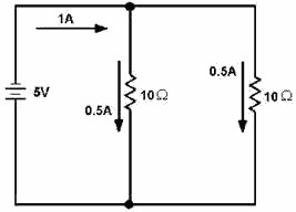
3-58 I3 is 2 amperes and its positive sign shows it to be a current entering the junction. Q34. There is a relationship between total current and current through the individual components in a circuit. What is this relationship in a series circuit and a parallel circuit? Q35. In applying Kirchhoff's current law, what does the polarity the current indicate? Resistance in a Parallel Circuit In the example diagram, figure 3-44, there are two resistors connected in parallel across a 5-volt battery. Each has a resistance value 10 ohms. a complete circuit consisting two parallel paths is formed and current flows as shown.
Figure 3-44. - Two equal resistors connected in parallel. Computing the individual currents shows that there is one-half an ampere current through each resistance. The total current flowing from the battery to the junction the resistors, and returning from the resistors to the battery, is equal to 1 ampere. The total resistance the circuit can be calculated by using the values total voltage (ET) and total current (IT). Note: From this point on the abbreviations and symbology for electrical quantities will be used in example problems. Given:
Solution:
3-59
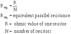
This computation shows the total resistance to be 5 ohms; one-half the value either the two resistors. Since the total resistance a parallel circuit is smaller than any the individual resistors, total resistance a parallel circuit is not the sum the individual resistor values as was the case in a series circuit. The total resistance resistors in parallel is also referred to as EQUIVALENT Resistance (Req). The terms total resistance and equivalent resistance are used interchangeably. There are several methods used to determine the equivalent resistance parallel circuits. The best method for a given circuit depends on the number and value the resistors. For the circuit described above, where all resistors have the same value, the following simple equation is used:
This equation is valid for any number parallel resistors EQUAL Value. Example: Four 40-ohm resistors are connected in parallel. What is their equivalent resistance? Given:
Solution:
Figure 3-45 shows two resistors unequal value in parallel. Since the total current is shown, the equivalent resistance can be calculated.
3-60
|
||||||||||||||||||||||||||||||||||||||||||||||||||
