Filter Transfer Functions

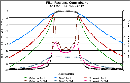
An infinite number of filter transfer functions exist. A handful are commonly used as a starting point due to certain characteristics. The table following the plots lists properties of the filter types shown below. Not given - due to complex numerical methods required -  are the Cauer (Elliptical) filters that exhibit equiripple characteristic in both the passband and the stopband.

Phase information may be gleaned from the transfer functions by separating them in to real and imaginary parts and then using  the relationship:

Phase:   θ =  tan-1 (Im / Re)

Group delay is defined as the negative of the first derivative of the phase with respect to frequency, or

Group Delay:      RF Cafe: Group delay formula

RF & microwave filter comparative responses chart - RF Cafe

Type Properties Transfer Function (Lowpass)
Butterworth
  • Maximally flat near the center of the band.

  • Smooth transition from passband to stopband.

  • Moderate out-of-band rejection.

  • Low group delay variation near center of band.

  • Moderate group delay variation near band edges.

  • Table of poles for N=1 to 10.

RF Cafe - Butterworth filter prototype transfer equation

Chebyshev

Type 1

  • Equiripple in passband.

  • Abrupt transition from passband to stopband.

  • High out-of-band rejection.

  • Rippled group delay near center of band.

  • Large group delay variation near band edges.

  • Table of poles for N=1 to 10.

RF Cafe - Chebyshev filter prototype transfer equation

Bessel

  • Rounded amplitude in passband.

  • Gradual transition from passband to stopband.

  • Low out-of-band rejection.

  • Very flat group delay near center of band.

  • Flat group delay variation near band edges[1].

  • Table of poles for N=1 to 10.

RF Cafe - Bessel filter prototype transfer equation

Note: BN, PN, and boN must be placed

          in a loop from 0 through N.

Ideal

  • Flat in the passband.

  • Step function transition from passband to stopband.

  • Infinite out-of-band rejection.

  • Zero group delay everywhere.

RF Cafe - Ideal filter prototype transfer equation

(Heaviside step function)

[1] Filters with a large BW will exhibit sloped group delay across the band. This usually is not a problem since group delay deviation tends to be specified for variation in some subsection of the band.
Band Translations
These equations are used to convert the lowpass prototype filter equation into equations for highpass, bandpass, and bandstop filters. They work for all three functions - Butterworth, Chebyshev, and Bessel. Simply substitute the highpass, bandpass, or bandstop transformation of interest for the fr term in the lowpass equation.

RF Cafe - Filter translation equations lowpass highpass bandpass bandstop

Click for more detailMicrowave Filters, Couplers and Matching Network

by Robert J. Wenzel

This CD-ROM course contains approximately 12-hours of instruction on the fundamentals of microwave filters, couplers and matching networks. Included is a thorough review of the common types of filter responses and calculations, filter realization, and various methods of filter design, including bandpass, network theory and Kuroda. Subsequent sessions cover the fundamentals of directional couplers. A final session describes distributed element matching networks and a matching network design example.

Related Pages on RF Cafe

- Butterworth Lowpass Filter Gain, Phase, and Group Delay Equations

- Butterworth Highpass, Bandpass, & Bandstop Filter Gain, Phase, and Group Delay Equations

- How to Use Filter Equations in a Spreadsheet

- Filter Transfer Functions

- Filter Equivalent Noise Bandwidth

- Filter Prototype Denormalization

- Bessel Filter Poles

- Bessel Filter Prototype Element Values

- Butterworth Lowpass Filter Poles

- Butterworth Filter Prototype Element Values

- Chebyshev Lowpass Filter Poles

- Chebyshev Filter Prototype Element Values

- Monolithic Ceramic Block Combline Bandpass Filters Design

- Coupled Microstrip Filters: Simple Methodologies for Improved Characteristics