Electronics Fundamentals
|
|
This "Electronics Fundamentals" material is from the U.S. Air Force's Air University collection of tutorials (Course 3050, dated 1960). It was found in a bin at Goodwill, bound along with a few other sections by the Extension Course Institute including Introduction to Radar and Television Principles. A few days ago I posted the Introduction to Radar section. A very thorough introduction to electric principle is presented, and is as useful as any modern text on the subject. Note in figure 21 that current flow (electron flow, or EF) is depicted as going from negative to positive, which is the correct physical model. Prior to World War II, current flow was considered to be from positive to negative; that scheme is now called conventional current flow (CCF). At semiconductor boundaries there is a sort of flow from positive to negative called "hole" current. A "hole" is the absence of an electron in an atom's valence bands, but that's a phenomenon barely known back in the 1940s, and is not covered herein. Electronics Fundamentals Course 3050 - Air University Volume 1 Introduction, Review of Algebra, and Elements of Electricity
Prepared by Keesler Air Force Base, Mississippi, Air Training Command Extension Course Institute, Gunter Air Force Base, Alabama Preface A few years ago not many people outside laboratories had even heard of electronics. Today, though, everybody knows that electronics opens garage doors as you drive up to them, that it brings Milton Berle into your living room, that it enables guns to fire automatically on unseen targets. Since you've signed up for Course 3050, Electronics Fundamentals, we assume you're interested in electronics. Yet you have to toddle before you can walk, you have to walk before you can run; and so we're trying to qualify you to enter any basic course in electronic equipment maintenance that requires a fundamental knowledge of electronics. Here's what you're going to study: essential mathematics; direct current sources and circuits; alternating current generation and circuit analysis; vacuum tubes and vacuum-tube circuits, such as timing circuits, sweep circuits, and wave-shaping circuits; receiving and transmitter theory; cathode-ray tubes and cathode-ray tube circuits used to make radar indicators; transmission lines and wave guides; and antennas. That's quite an order, isn't it? Well, to get you started right in your early study and to give you the dope you need for later volumes, we introduce you in Volume I to radar, review elementary algebra, and discuss the elements of electricity. Now for some study tips.
Keep this pamphlet for your own use. We estimate that the time required for the average student to complete Course 3050 is 300 hours. The credit value of the course is 300 hours (100 points). This volume is valued at 33 hours (11 points).
Chapter 3 - Elements of Electricity In our last two chapters we have introduced you to radar in a pretty general way and covered the algebra you will need for the next few lessons. In this chapter, we are going to present something equally important, the fundamentals of electricity. Here's how we go about it. So we'll have some common ground on which to measure quantity, we first tell you about the centimeter-gram-second system of measurement. From there we move into a discussion of the nature of matter and the structure of atoms, and then into an explanation of electricity as a flow of free electrons in a conductor. Since we refer throughout the course to the direction of electron flow, we show you how it's different from conventional current flow. To you, we probably seem to be emphasizing everything, and in a way we are, but for later parts of the course you have to understand thoroughly electrical charges and the electrical field. Of great importance too are the ideas of potential difference and electromotive force. On the practical side, you will learn the distinction between conductors and insulators, the coding of resistors by color, the resistance of wire, and the use of meters. That information is very necessary, as you'll be using it as long as you study and work with electricity and electrical circuits. Everything considered, you've really got some knowledge to master in this chapter; so you can't slide through it. Let's go! 31. Some Fundamental Ideas You've seen the rains splatter on the roof, maybe you've watched the tide roll in from out at sea, waited for a tree in the forest to fall. Or perhaps you've fished from a river bank and noticed the current push down toward~ the sea; most of us have seen a fire sweeping across some pine forest. But whatever you observed in nature had three things in common with every other occurrence: It took time for it to happen, it happened some place (space), and it involved quantity (or mass). Your observation of nature has most likely been rather haphazard. Few of us watching nature in action are interested in precise measurements of either time, space, or quantity. Now. though, we are going to move from this casual noticing of natural events into the scientific discussion of them. In order to discuss them intelligently we need some scheme of measurement which is used pretty universally. So let's see how length, mass, and time are measured in the physical sciences. One system used frequently is the centimeter-gram-second {C.G.S.) system of units in which the centimeter is the unit of length; the gram, the unit of mass; and the second, the unit of time. Throughout this course that's the system we are going to use. For one thing, it is used by scientists allover the world; for another, it is far more convenient than the footpound-second system, mostly because its numbers are multiples of ten instead of the 36 inches to a yard, 16 ounces to a pound of the other system. To have some idea of the relative size of units in the C.G.S. system as compared with the footpound-second system we use every day, look at the following comparisons: 1 yard = 91.44018 centimeters 1 inch = 2.54M5 centimeters 1 pound = 453.59 grams Now glance at a few of the relations between units within the C.G.S. system: 1,000 millimeters = 1 meter 1,000 milligrams = 1 gram 1,000 milliseconds = 1 second 1,000,000 micrograms = 1 gram 1,000,000 microseconds = 1 second 1,000 meters = 1 kilometer 1,000 grams = 1 kilogram 100 centimeters = 1 meter Of course you noticed that all these measurements are in nice round numbers. Let's look a little more closely at the numerical pattern they follow. You see that 1,000 millimeters = 1 meter, that 1,000 milliseconds = 1 second, that 1,000 meters = 1 kilometer. What does that tell you? That one millimeter is one-thousandth of a meter, etc. Sure. But it also tells you that the prefix "milli" means "thousandths of," and if you'll look closer you'll see that the prefix "kilo" means "thousands of" and the prefix "micro" means "millionths of." You'll agree that once you get the simple relationships fixed, this system is much easier than the" one we used in the grocery store or the piece goods shop. Having in mind the system by which we identify the passage of time, length, and mass, you need no some definitions of the basic terms we shall use while studying electricity. While you don't have to memorize these right this minute, you should read them carefully and note where they are in the text for future reference. Mass is a measure of the quantity of matter in a body. In the C.G.S. system, we measure mass by grams. Force is that which produces or attempts to produce a change in motion. The unit of force is the dyne, which is slightly more than the weight of one milligram at the earth's surface. Work is the production of motion against a resisting force. When a body - a wagon, a freight car, a lawnmower - is moved work is done. The unit of work is the erg, which is the work done when a force of one dyne moves through a distance of one centimeter. Because the erg is a very small unit, a larger unit known as the joule, equaling ten million ergs, is frequently used. Energy is the capacity to do work. Energy that is due to the motion of a body is called the kinetic energy of the body, while energy due to the position of the body is called the potential energy of the body. We see energy being manifested in the forms of heat, light, and motion, and it can be transformed from one form to another by mechanical, chemical, and other means. Since energy is the capacity to do work, we measure energy and work in the same units. Power is the rate of doing work. A given amount of work may be done either in a short or long time; and in commercial operations the rate of working, or the work done per second or hour, is an important consideration. One unit of power would be a joule per second, which is called a watt. Since power is the rate of doing work or of consuming energy, the length of time power is being used is the true measure of energy consumed. Most of us buy electrical energy in units called watt-hours (watt times hours). But this unit is so small that a larger unit, the kilowatt-hour (one thousand watt-hours) is used for metering (and billing electrical energy consumed. The common 100-watt lamp, for example, requires 100 watts of power for proper operation and consumes 100 watt-hours of energy in one hour. In ten hours of operation the lamp would consume 1 kilowatt-hour of energy. That's the unit you pay for on your electric bill. 32. The Nature of Matter People used to have an easy time describing matter. They said it was either solid, liquid, or gaseous, and let it go at that. Today' s scientists, however, aren't satisfied with such a flip grouping and have broken matter down into much smaller divisions. Preceding all of the modern theories about matter was the Greeks' idea of it, though. Convinced that all physical things consisted of four "elements" - air, earth, fire, and water - the Greeks believed that materials differed because they were composed of varying amounts of these four elements. How simple indeed must have been the study of chemistry and physics in those days! Some four or five hundred years ago, the Greeks' theory began to be discredited, and their four elements have since been broken down into more and more substances, still called "elements," but nothing like the easy fire, air, water, and earth theory of the ancient Greeks. An element, as you may remember it from high school chemistry, is a substance which cannot be reduced to a simpler substance by chemical means, like iron, gold, silver, copper, oxygen, etc. Matter, on the other hand, may be composed of either a single element or a combination of elements. When we combine elements, we do it in a couple of ways. One is the chemical combination or compound (such as water or salt), consisting of two or more elements which cannot be separated by physical means. The other is the physical combination or mixture (such as milk or brass) consisting of two or more elements or compounds which can be separated by physical means. Before long, we'll further explain these differences. Scientists, as you've probably read, are never satisfied with yesterday's success. So in recent years they have been able to find out still more about elements. They have found that elements can be reduced until only a minute particle of matter remains, and have called the smallest particle of an element that still contains all its original characteristics an atom. They have gone even further and labeled the smallest particle of a chemical compound that contains the original characteristics of the compound a molecule, and told us that a molecule is a particle composed of at least two atoms.
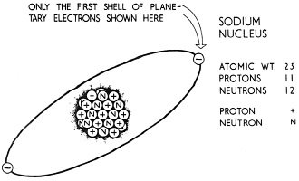
Fig. 11 - Nucleus and first shell of an atom of sodium.
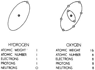
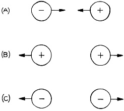
Fig. 12 - Atoms of hydrogen and oxygen. 33. The Structure of Atoms To reduce any material down as far as atoms probably seems like a smart operation to you, and it is. But the searchers in laboratories turned up more. than that. They found that the atom itself consists of many smaller particles, the basic ones being the proton, the electron, and the neutron. And then by experiments too complex for us to consider here, the diameter of an atom was measured as being on the order of 0.000000004 inch. Near the center of the atom is the nucleus, a comparatively compact group of protons and neutrons. If you'll look now at figure 11, you'll see a cluster of protons (+'s) and neutrons (n's) with the electrons whirling around in an orbit. These electrons revolve around the nucleus of the atom in orbits or shells spaced at varying distances from the nucleus; and because they are like the planets of the solar system revolving around the sun are often referred to as planetary or orbital electrons. Let's compare the size of the nucleus and the atom. You remember that we needed eight zeros to the right of the decimal to give the diameter of the atom. When we express the diameter of a nucleus, we need more than eight; we use thirteen zeros, like this - 0.00000000000004. Or we could say it this way: The diameter of the atom is about one hundred thousand times the diameter of the nucleus. The atom, then, is mostly empty space. The diameter of each electron surrounding the nucleus, we should point out, is about the same size as the nucleus. You remember from figure 11 that a nucleus is composed of protons and neutrons. What makes the difference between atoms of one , element and those of another is the number of protons in the nucleus. Look now at figure 12 showing a hydrogen and an oxygen atom. The hydrogen atom with one proton in its nucleus has one electron revolving around in an orbit. The oxygen atom, however, with eight protons in. its nucleus, has eight electrons revolving around the nucleus. These examples illustrate an important physical law: In an atom with its normal number of electrons, the number of protons in the nucleus is exactly equal to the number of electrons revolving about the nucleus. We said a minute ago that the diameter of each electron surrounding the nucleus is about the same size as the. diameter of the nucleus. That's quite true, but the weight of the nucleus far exceeds that of the electron. IJ1. fact, a proton alone is about 1,840 times as heavy as the electron and there are many protons in the nucleus of some atoms. 34. Electrons With that general information about the structure of atoms, you are ready to learn more about electrons, for it is the electron, not the nucleus or its particles, that is most important in the study of electricity. Here are some of the qualities of the electron. Unlike protons or neutrons, which require tremendous force to be separated from the nucleus, electrons can be detached from the atoms of many substances. Once detached, an electron shows none of the properties of ordinary matter. Nor does it react chemically with other electrons to produce some new substance. In addition, all electrons are alike and act in precisely the same way whether extracted from atoms of hydrogen, copper, tin, or any other substance. In short, the electron seems to be nothing but electricity. Even so, it has a definite rest mass of approximately 0.00000000000000000000000000091 gram (those are twenty-seven zeros ahead of the 9). 35. Charged Bodies We sometimes think that electricity is a brand new discovery, because most of its applications are. Yet some 600 years before Christ, Thales, a Greek philosopher, discovered that when amber, a yellow-to-brown fossil resin, was rubbed with a piece of cloth, it attracted certain light materials, just as a magnet attracts bits of iron. Would you like to duplicate Thales' findings? You can, by using a piece of hard rubber instead of amber. Also get yourself two or three bits of paper, each about 1/8 inch square, and a hard rubber comb or other hard rubber object. Rub the comb briskly with wool (if your coat is wool, it'll do), and bring the comb close to the bits of paper. All of a sudden the bits of paper will jump toward the comb and cling to it for some time, even if the comb is held in mid-air. And what have you done? When you rubbed the comb with the wool cloth you produced a form of electricity. Our words electricity and electron come from the Greek word, "electron," meaning amber. So every time we talk about electricity, we're really going back twenty-five and a half centuries. As you may remember from your history books, all learning was pretty much the property of the Church until about four or five hundred years ago. But with the rekindling of interest in science beginning around 1600 experimenters tried to determine the cause of the occurrence described above. In dabbling with various substances, they found other materials-glass, rubber, sealing wax - with characteristics like amber. They learned, for example, that when a glass rod was rubbed with silk and suspended:'.0 as to swing freely, it would swing away from another glass rod similarly treated' when the second rod was brought close to it. And so they stumbled upon the law of repulsion: that two objects charged the same way repel each other. The law of attraction came next. When a glass rod rubbed with silk was approached by a hard rubber rod that had been rubbed with fur or wool, the g lass rod moved toward the rubber rod. But when unrubbed rods were brought close together, nothing happened - neither repulsion nor attraction. Obviously, the rubber and glass rods were different after being rubbed. The difference was that they were electrically charged. Not every one fooling with this primitive electricity was aware of this, of course. Ben Franklin, the American who proved wrong the old saying, "jack of all trades, master of none," figured it out first. Noting that a charged rubber rod attracted the suspended charged rod but that another charged glass rod repelled it, he concluded that the charges on the rubber and glass rods were of opposite kinds. Having to identify the charges some way, he arbitrarily called the charge on the rubber rod "negative" and that on the glass rod "positive" to show their opposition. As many times as you've heard those terms, you probably never realized how long it took for our ancestors to find out the simple truth underlying them: That bodies with like charges repel each other, and those with unlike charges attract each other. You may also have heard the term "static charges. "That term describes charges not in motion but at rest, and their study is called "electrostatics." That's all we're going to say about those terms right now, however. 36. The Nature of an Electric Charge From the preceding section you know that Franklin assigned the word "positive" to the charge on a rubbed glass rod and the word "negative" to the charge on a rubbed rubber rod. That at least gave scientists a way to talk about charges. After Franklin, other investigators concluded that when the glass rod was charged by rubbing with silk, a number of electrons were removed from the glass by the friction between the g lass and the silk, leaving the glass with less than its normal number of electrons, and giving the silk more electrons than before. Remembering that the glass rod is positively charged and that it has fewer electrons than it had before it was rubbed, we can now define any positively charged body as one deprived of some of its electrons. This being true, we can go a step further and say that an excess of electrons gives a body a negative charge. The silk, for example, is negatively charged, having an excess of electrons. When you put all this together, you say this: Taking away electrons makes a body positive; adding electrons makes it negative. Or imagine if you can an exactly balanced scale representing a body with the protons and electrons in perfect equality. Imagine that the left dish is filled with so many electrons, the right with the same number of protons. The minute electrons are taken off the left dish, it goes up, corresponding to the positive charge of a material deficient in electrons. But if electrons are added to the left dish, it drops, corresponding to the negative charge of a body with an excess of electrons. Electrons, then, have to be a unit of negative electrical charge. Dr. Robert A. Millikan and others, by computing the value of this charge, have shown, in addition, that it's the smallest known unit of negative electric charge and cannot apparently be subdivided. A little while ago we said that an atom or molecule with the normal number of electrons is electrically neutral, being neither positively nor negatively charged. Because the electrons are negative, the nucleus of a neutral atom must contain positive charges to balance those negative charges. Experiment has confirmed this conclusion and a further one, that the protons are the required positive charges. Each t us is a unit opposite chare equal in magnitude but opposite in kind to the negative charge of the electron. So "free" protons, that is, protons not attached to any nucleus, will repel each other just as "free" electrons repel each other. And a proton, being a positive charge, will attract an electron. In passing, we should mention that the neutrons are just what their name suggests, electrically neutral. Once they were thought to be combinations of a proton and an electron, but recent research has convinced most scientists that it is impossible for an electron to exist as such within the nucleus. By now, maybe a couple of questions have run through your head about this whole business of electrons and protons. Why, you might well ask, if the nucleus is positively charged and the electrons negatively, aren't the electrons pulled into the nucleus by the attractive forces of unlike charges? Or, if positively charged protons are inside the nucleus, why doesn't the nucleus fly apart, since like charges repel each other? Those are good questions. Now we'll try to answer the first one for you. Normally, the electrons and the protons should attract each other, but the electrons also have a force working on them trying to pull them away from the nucleus. Developed from the whirling action of the electrons, this can be called a centrifugal force. Naturally, the result of these two forces keeps the electron in a balanced position whirling furiously around the nucleus. This action can be duplicated by whirling a ball attached to a string. The ball will tend to pull away from you, but because you are pulling on the string, the ball circles around in a fixed path or orbit. As for the second question, why don't the protons repel each other? Well, there is a superforce which exerts a tremendous cohesive countereffect to this positive force. This uniting countereffect keeps the protons in their places. But remember there is always the possibility they will break loose. As if for further security, the neutrons, which you remember are also in the nucleus, act as buffers between the protons because they have no electrical charge. The more protons in the nucleus, the more neutrons are needed to keep the protons together. Also, the more protons there are, the greater the superforce needed to keep them from throwing each other out of the nucleus. Let's emphasize another point. A body composed of many atoms. and molecules is not positively charged because it possesses three protons than usual but because it has fewer electrons. More stable than electrons, protons cannot be added to or taken away from an atom or molecule by the simple process of rubbing two bodies together. Even though electrons are removable and even if there are a great number of electrons associated with an atom or molecule, to remove more than one electron is generally difficult, and that one from the outermost orbit--electrons in the inner orbits are very difficult to remove. Although a body may be positively charged. most of its atoms are neutral, with their normal number of electrons; other atoms have had just one electron removed. If only a few of the atoms have had an electron removed, the body has a small charge - the more electrons that have been removed the higher the positive charge. We can't remind you too often that electrons are negative. To describe an atom or molecule whose electrons are not equal to its protons, we use the term ion. And in keeping with everything we've said before, an atom or molecule with more electrons than protons is a negative ion; one with more protons than electrons is positive. When you remove electrons from or add them to an electrically neutral atom or molecule, the process is known, not surprisingly, as ionization. Now let's see what you've learned about the nature of an electrical charge. First, we've said several times that the number of electrons in an electrically neutral atom or molecule is equal to the number of protons. Second, we told you that it's very difficult to remove a proton from the nucleus or to remove an electron from an inner orbit. Third, it is possible, however, to add electrons to the outermost orbit of an atom or to remove one from it. Electrons not attached firmly to any atom are called "free" electrons. Fourth, you should never forget that a negatively charged body has an excess of electrons, while a positively charged body has a deficiency of them. 37. The Unit of Electric Charge Knowing how tiny an electron is you can realize why its charge is far too small to be convenient as a unit of electric charge. As a workable figure, a charge of 2,100,000,000 electrons has been established as one unit of charge. Called the electrostatic unit, it is abbreviated "e.s.u." This means that if the charge of a body is 10 e.s.u., 10 x 2,100,000,000 excess electrons are on a negatively charged body and that the body has lost the same number of electrons if the charge is positive. Let's look at the e.s.u. a different way, as it relates to force. The electrostatic unit is that quantity of electricity which, concentrated on a small sphere in a vacuum, repels an equal charge one centimeter away with the force of one dyne. (Remember that a dyne is slightly more than the weight of one milligram, a thousandth of a gram, at the earth's surface. ) This definition enables us to measure with accuracy the amount of charge on each body. 38. Coulomb's Law for Electric Charges From what we've covered up to this point, you know that a force exists between charged bodies. In the Eighteenth Century, a physicist named Coulomb worked out a formula for figuring the force exerted upon two small charged spheres separated by a distance larger than t he diameter of the spheres. According to his law, the force which the charges exert on the spheres is directly proportional to the magnitude of each charge and inversely proportional to the square of the distance between the centers of the spheres. Just to see how the law works, we'll consider the charged spheres as being in air. Here's how Coulomb's law looks as a mathematical formula: F = (q1 q2) / d2, q1 is the charge in e.s.u. on one body, q2 the charge in e.s.u. on the other, d the distance in centimeters between the centers of the spheres, and F the force in dynes exerted upon the spheres. Applied, the formula looks like this: Problem 1. What force is exerted upon two charged spheres in air if one has a positive charge of 25 e.s.u.. the other a negative charge of50e.s.u., and the distance. between the centers of the spheres is 5 centimeters? Solution. Let q1 = 25 e.s.u. and q2 = 50 e.s.u. Then, F = (25 x 50)/52 = (25 x 50)/25 = 50 dynes. Because the spheres are oppositely charged, they attract each other. 39. Electric Field of Force Back in the introduction we referred to the electric field of force as one of the important things you were to learn about in this chapter. Now is a good time for us to see what we mean by this term. If you touch a light substance, such as a pith ball, (a ball made out of the light core, or pith, of certain plant stems) to a charged glass rod, it acquires a positive charge like the glass rod. Since bodies possessing like charges repel each other, the pith ball will be repelled from the glass rod. But you'd like to know why-here's the answer. When the pith ball, electrically uncharged, was touched to the glass rod, a few of the electrons passed from the ball to the rod, leaving both positively charged and creating the force of repulsion. Not only that, but the repelling force between the pith ball and the glass rod exists even when there is considerable distance between them. The space surrounding a charged body, therefore, in which another charged body is acted upon by a force urging it to move, is called the electric or electrostatic field of force. This electric field surrounds every charged body and extends in all directions from it. 40. Lines of Force Of course we can't see the electric field of force, but we can make a suitable graphic illustration of its properties by following the method of the British scientist, Michael Faraday, who drew lines from a charged body into the surrounding space, calling them" lines of force" or "lines of electric intensity." The direction of the force, shown by arrows on the lines, is the direction that a positively charged body would be urged to take if placed on a line. The closeness of the lines in various parts of the diagram shows the relative strengths of the field. In other words, where the lines are close together the field is more intense than where they are further apart. To see" lines of force yourself, sprinkle some iron filings on a card and lay the card over a magnet. The filings arrange themselves so you can first see the direction of the magnetic stress; then, by observing the closeness of the groupings, you can figure out where the field is most intense.
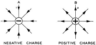
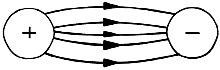
Fig. 13 - Electrostatic fields around isolated charges.
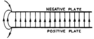
Fig. 14 - Electrostatic field between plates with opposite charges.
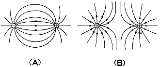
Fig. 15 - Lines of force between bodies with equal charges. A. Bodies with unlike charges. B. Bodies with like charges. We say also that a line of force or originates on a positively charged body and ends on some negatively charged body, even though it may not be convenient in a drawing to indicate both charges. In drawings like figure 13, it's understood that each line of force begins on some positively charged body and ends on a negatively charged body. One point we want to underline here - while the direction and magnitude of the electric forces are represented by lines of force, the electric intensity is not confined to the actual lines but is present at every point in the region or space around the charged body. Now let's look at the electric field between two parallel metallic plates, one of which has been charged positively and the other negatively, as on figure 14. All lines of force are properly shown as beginning on the positive plate and as ending on the negative plate. The two plates have been given equal charges, that is, as many extra electrons have been deposited on the negative plate as have been taken away from the positive plate. The field, you notice, is very intense between the two plates, weaker beyond the edges, and very weak in the space not included between the two plates. Two lines of force, furthermore, cannot intersect, for if they did, a point charge placed at their point of intersection would move in two different directions at the same time. Suppose we turn to figure 15(A), which shows the lines of force between equal positive and negative charges on two small spheres in air. Note that the lines start on the positively charged sphere and end on the negatively charged one. Remember too that Faraday explained the attraction and repulsion between charged bodies by assuming that the lines of force, in a state of tension, contract lengthwise and repel each other sidewise. As the lines get shorter, therefore, the spheres are pulled together. When we study figure 15(B) with its two positive charges, we discover, on the other hand, that the lines repel each other and push the spheres apart. If you have this clear, we should remind you that there are no actual lines of force. We use the idea of lines to enable us to picture the field of force, and so when we speak of them as contracting lengthwise and repelling sidewise, we are just using them to show visually the forces which exist between bodies electrically charged. Since we've covered about a third of the information which we're going to present in this chapter, this is as good a time as any to see where we stand. You probably think that this third has been pretty complicated stuff. And if you've never studied any electricity, it undoubtedly has been tough. So if you're hazy on anything discussed up to here, we suggest you go back right now and go over it again. For now we're going to start talking about the applications of these 41. Electric Current In preceding sections we learned that if a body has an excess of electrons it's charged negatively and if it has a deficiency of them it's charged positively. So when two differently charged bodies are connected by a wire, electrons will flow from the body having the negative charge to the one having the positive charge. Moreover, the flow will continue until a sufficient number of electrons has passed from the negatively charged body to neutralize the positive charge on the other and then will cease. The movement doesn't take long; in fact the electrons are transferred so fast that we say the flow is instantaneous. This flow of electrons is electric current, the energy that dances through the filament of an electric light bulb, that fires up the heating element in an electric toaster, and makes possible the electromagnetic waves in a radar set, our baby. How much current goes through a wire depends on the number of electrons that pass a point on the wire in a given interval of time. So small are electrons and the charge on each that only enormous numbers of them will furnish a useful unit of charge. You recall that back in section 38 we told you about the electrostatic unit (e.s.u.) of 2,100,000,000 electrons. Well, we have an even more practical unit than that, the coulomb (named, of course, after the Eighteenth Century physicist), which is the electrical charge of 6,280 million billions of electrons. We go further and relate the coulomb to time saying that when one coulomb of electricity passes by a given point in one second, the magnitude of current flow is one ampere. The rate of flow is represented by capital I if the magnitude is constant, but by small i if the magnitude varies. The unit of current, the ampere, is designated either by the abbreviation amp or by the letter a. In everyday language, a 100-watt light bulb has a current of about one ampere flowing through it. Also on the practical level, let's see now what the three principal means of detecting an electric current are. (1) When a current is flowing in a conductor, any part of the conductor will affect a compass needle brought near it. We call this the magnetic effect of an electric current. (2) When current is flowing in a circuit, heat is developed in all parts of the circuit. As the current increases, the temperature of each part of the circuit increases. So we can detect current by its heat effect. (3) We can also detect a current by observing its chemical effect. When two copper plates are dipped in a solution of copper sulphate and connected to the terminals of a battery so that a current flows in the circuit, metallic copper leaves the solution of copper sulphate and is deposited on the copper plate connected to the negative terminal. The amount of metal deposited in a given time is proportional to the total quantity of electricity passed through the solution. 42. Conductors and Insulators We've seen that the movement of electrons produces electric current. However, not all materials let electrons flow through them easily, To describe the ease with which a current may pass, a couple of terms are common. A material, for instance, through which an electric current may pass with little opposition is called a conductor of electricity. But a material that offers relatively great opposition is called a nonconductor, an insulator, or a di-electric. Even so, no known material , is a perfect conductor and none is a perfect insulator, because all substances offer some opposition to the passage of current and all let some current pass. Whether a material is a good conductor depends on how its electrons behave. Those materials which we classify as conductors possess a great number of electrons that are either "free," that is, not bound to any atom, or else are very loosely bound to the atoms of the material. Insulators, on the contrary, possess relatively few free electrons, and those that are bound to atoms are hard to remove from even the outer orbits. As you would expect, conductors are widely used in all sorts of electrical equipment. After all, you have to get current from one place to another. In a radar set, for example, copper wires bring the current from a generator to the set. The capacity of a material to transmit an electric ~current (those billions of electrons we referred to awhile ago) is conductance" based on the number of free electrons in a given volume of the material. There are some other terms you need to know. We refer to conductance in formulas by the letter G and we call the unit by which we measure it a mho (ohm, which you'll meet in a minute spelled backwards). It's just like we use the word "water" to stand for the liquid but when we start talking about its quantity we use "gallon." To get back to the mho - a piece of copper wire one-tenth of an inch in diameter and 1000 feet long has a conductance of one mho. You probably didn't need us to tell you that there is no such thing as a perfect conductor of electricity. Anybody who's the least bit practical has heard that. Not surprisingly, we call this always-present opposition to the flow of electrons resistance. In the last paragraph we said that the letter G stands for conductance; well, for resistance, we use the letter R, and the unit of measurement is the ohm, which is the resistance of a piece of copper t wire 264 feet long and 0.05" in diameter. Or if this means more to you - a110-volt, 50-watt lamp in full operation has a resistance of 242 ohms. Numerically resistance is the reciprocal of conductance. From your last chapter, you'll remember that R = 1/G (also that RG = 1 or G = 1/R.). To apply that simple formula, let's figure the conductance of an electric toaster or electric iron, both of which have a resistance of about .25 ohms. Here's how it would look. 1/G = .25 25 G = 1 G = 1/25 mho Perhaps you got the impression from the above that resistance is undesirable. Sometimes, it is true, we don't want resistance, say in a long transmission line. But in other installations, we need it. To get this opposition to the flow of current, we put in special devices called resistors. A radar set, for example, contains lots of different sizes and types of resistors, which we'll discuss in later sections. If you aren't looking for resistance but $ for conductance, however, the best metallic ~ conductor of an electric current is silver. After silver, comes copper, then gold, aluminum, tungsten, zinc, iron, platinum, steel, and tin - arranged in the order of decreasing conductivity. Of the insulators, glass is one of the best insulators at normal temperatures. Others are rubber, mica, certain types of varnish, and paraffin. Air, too, is an excellent insulator, although, like all others, it's not a perfect one. 43. Wire Resistance Because copper is one of the best conductors of electricity, it is used all the time in electrical wires. Most of us, in fact, when we think of an electrical wire automatically expect it to be made of copper. Aluminum is used pretty widely too, however, as it is not only a good conductor but also a light material. For insulation', either a rubber compound or varnished cambric is used. As good a conductor as copper is, it, like all other materials, still offers some resistance to the flow of current. Regardless of the conductor used in a wire the resistance of the wire depends on two things, its length and its diameter. Let's state this important principle this way: The longer the wire, the greater its resistance; the larger the diameter of the wire, the less its resistance. In other words, if two wires made of the same material have equal cross-sectional areas but one is twice as long as the other, the longer wire has twice the resistance of the shorter. Or if two similar wires have equal lengths but the cross-sectional areas of one is one-third the cross-sectional area of the other, the smaller wire. has three times as much resistance as the larger one. Now, see what you can do with the following problems before looking at the solutions. Example 1. Two copper wires A and Bare the same diameter but wire A is twice as long as wire B. Find the resistance of wire' B if wire A has a resistance of 5 ohms. Solution. Since wire B is one-half the length of wire A, it will have one-half the resistance of wire A. Therefore, the resistance of B is 2.5 ohms. Example 2. Two copper wires x and y having circular cross-sections are the same length but the diameter of x is twice that of y. If y has a resistance of 4 ohms, what is the resistance of x? Solution. Since y is the smaller wire, its resistance will be greater than the resistance of x. If d1 = the diameter of x, then d1/2 = the diameter of y. Let A1 = the cross-sectional area of x and A2 = the cross-sectional area of y. Since A1 = πr12 = π(d1/2)2 = πd12/4 and A2 = πr22 = π(d1/4)2 = πd12/16 then A1 = 4A2 Therefore, the resistance of x will be one-fourth the resistance of y. Since the resistance of y is 4 ohms, the resistance of x is 1 ohm. Example 3. Two wires x and y are made of identical materials. Wire x is twice as long as y and the cross-sectional area of y one-third the cross-sectional area of x. If y has a resistance of 12 ohms, what is the resistance of x? Solution. The resistance of x is 2 times (1/3) that of y since the length of x is twice that of y, and the cross-sectional area of x is three times that of y. Since the resistance of y is 12 ohms, the resistance of x is 2(1/3) (12) = 8 ohms. 44. Resistors One important law of resistance relates, then, to the length and diameter of the conductor. Yet another characteristic of some materials, such as metals, is that their resistance increases with the temperature of the material, and, within practical limits, the change in resistance is usually directly proportional to the change in. temperature. For example, a copper wire of the proper dimensions will have a resistance of 100 ohms at 0 degrees C., a resistance of 100.85 ohms at 2 degrees C., and a resistance of 101.7 ohms at 4 degrees C. Carbon, we'll mention, is one of the few substances whose resistance decreases as the temperature increases.
Fig. 16 - Fixed resistors and their schematic symbol.
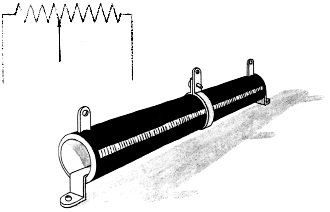
Fig. 17 - Adjustable resistor and its schematic symbol.
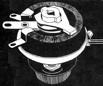
Fig. 18 - A variable resistor.
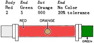
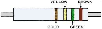
Fig. 19 - A system of color coding.
Fig. 20 - The RMA system of color coding. Although changes in temperature cause changes in the value of resistors, a fairly constant value of resistance may be placed in a circuit by using fixed resistors, that is, resistors whose opposition to the flow of electrons remains nearly constant. Figure 16 shows several types of fixed resistors and the corresponding symbol that we use in diagrams to represent any fixed resistor. Sometimes, though, you need to change or adjust the value of the resistance of the circuit. When this is true, adjustable resistors are installed. Normally, the adjustable resistor is wire-wound and has one or more sliding collars which may be moved along the resistance element to select the desired resistance value. After the desired value has been selected, the collars are then clamped in place. Figure 17 shows an adjustable resistor. In other circuits, resistance has to be changed so often that it would take too much time to unclamp, move, and refasten sliding collars. In these circuits we use variable resistors of either carbon or wire-wound construction, depending on the current that is to flow through them. The resistance element of the variable resistor 1S usually circular, and the sliding tap or arm which makes contact with it connects to a knob or shaft which is turned to vary the resistance smoothly. Variable resistors are generally called rheostats or potentiometers, according to their use. You've turned the volume control knob on a radio set many times, haven't you? When you do that, you are operating a variable resistor. In figure 18 you can see one type of variable resistor. 45. Color Codes To eliminate marking or stamping numerical values on fixed resistors, manufacturers use a system of coding resistors by Fig. 18. A variable resistor. color, particularly small-sized ones. Here's how the system works. The digits from 0 to 9 inclusive have the following color designations: Color (Number): Black (0), Brown (1), Red (2), Orange (3), Yellow (4), Green (5), Blue (6), Violet (7), Gray (8), White (9). We'll explain in a minute how these are combined to show so many ohms of resistance. Since manufacturers can hardly make a fixed resistor with exactly a given value of resistance, they also put on the resistor a color to designate the percentage variation or tolerance a resistor can be expected to differ from its stated value. These markings follow, the last three being the most common: Color (Tolerance): Brown (1), Red (2), Orange (3), Yellow (4), Gold (5), Silver (10), No Marking (20). Now let s glance at the two ways these colors are put on a fixed resistor. The first method puts the colors on the body of the resistor, on an end, and on a colored dot on the body. You should turn now to figure 19. The color of the body indicates the first figure of the value, the color on the end (or tip) indicates the second figure, and the color of the dot indicates the number of zeros that follows the first two figures. So we read figure 19 like this: Body = Red (2), End = Green (5), Dot = Orange (000), End = No Color (20% tolerance) Put together, the first three columns give us 25,000 ohms for the resistance. But we also have a 20% tolerance to take into account, which gives 5,000 ohms variation either way. This means that this resistor may have a resistance anywhere between 20,000 and 30,000 ohms, inclusive. That's a pretty good scheme, but the other method is even more common, since the Radio Manufacturers' Association has adopted it. The colors stand for the same numbers as in the other system; it's just that they are put on the resistor differently. As you can see in figure 20, this system uses bands instead of body color, dots, etc. The first band of color, the band nearest an end (or tip) of the resistor, indicates the first figure in the numerical value; the second band, the second figure; the third band, the number of zeros; and the fourth band, if any, the tolerance (as in the first system we described, no band means 20%). When bands of color are used, the body color, we should add, has no significance. Suppose right now you figure the numerical value of the resistance in the resistor shown in figure 20 before looking at our solution. (Be sure to start from the right. ) You should have this: First Band Brown (1), Second Band Green (5), Third Band Yellow (0000), Fourth Band Gold (5% tolerance) The resistance, therefore, is 150,000 ± 7,500 ohms. Fortunately, few places, if any, in a radar or radio set require a resistor of exact amount. Nearly every set will perform adequately if the resistors are within 20 percent of their stated values. On some band-marked resistors, the third band as well as the fourth may be gold or silver, particularly when the value of the resistance is less than 10. If the third band is gold, you multiply the number represented by the first two bands by 0.1; if the third band is silver, you multiply the number by 0.01. 46. Potential Difference So that you can understand the idea of potential difference more clearly, let's review some of the characteristics of electron flow. In, fact, we might even say that potential difference is just another way of labeling that occurrence, which we've already discussed. You remember that our calling a body negatively or positively charged contrasts it with its normal or uncharged state. To go a step further: If we connect a copper wire between two metallic spheres, A and B, both charged negatively but with A charged more highly than B (having a greater number of excess electrons than, B), electrons will flow along the wire from A to B, continuing to do so until the number of excess electrons on both spheres is equal. Before we connected the wire, however, sphere A was negatively charged with respect not only to its normal state but also to B. Sphere. B, on the other hand, was charged negatively with respect to its normal state but charged positively with respect to A, as it had fewer excess electrons than A. Or take this illustration. Let spheres x and y be charged positively, with x more highly charged than y. If these two spheres are connected by a wire, electrons will flow along the wire from y to x. The reason they flow that way is that x, being more highly charged positively than y, has been deprived of more electrons than y. As with A and B, the electrons will flow from y to x until both spheres have the same charge. Compared to their normal states, both x and y were positive; also x was positive in respect to y, while y of course was negative with respect to x. Electrons, you recall, flow from the negative to the positive. In general, electrons will flow momentarily along a connecting wire between two charged bodies if the bodies are charged either with different amounts of the same charge or with any amount of different charges. The only requirement is that one body be charged differently from the other. This difference in charge is potential difference. As with everything else in electricity, we must have a unit of measurement. For potential difference, the most common unit is the volt, that unit of potential difference which will cause one ampere of current V to flow through a resistance of one ohm. (Reminder: In any circuit, current is said to flow at the rate of one ampere when the magnitude of the electron flow pasta given point in the circuit is at the rate of one coulomb per second; an ohm is the resistance offered by 264 feet of copper wire 0.05" in diameter.) The potential difference of a dry cell is one and one-half volts; for an ordinary automobile battery it's six volts. We have some other terms which mean the same thing as potential difference and which we use interchangeably with it - electromotive force (emf), difference of potential (PD), electrical pressure (E), voltage (V), and voltage drop. But we normally use" electromotive force" when referring to the potential difference of a battery or other source of potential difference, while "voltage drop" and "difference of potential" usually refer to the potential difference between two points located on either side of a device, such as a lamp or resistor in a circuit.
Fig. 21 - Direction of electron flow in a circuit. 47. The Direction of an Electric Current As you probably know, a closed circuit is a continuous path through which current flows. We can make an electric circuit by combining an electromotive force (a battery), conductors (copper wires) and resistors (a light bulb) in such a way that they provide a continuous path for electrons to flow. Usually, too, a circuit has a switch to open and close it. Figure 21 shows an electric circuit. When we close the switch, the circuit closes. Opening the switch results in an open circuit, for the electron flow no longer has a continuous path but contains an air gap. Since air is a good insulator, no electrons will flow across the gap nor any current in other parts of the circuit. If you do have a closed circuit, though, a difference of potential determines the direction of electron flow. As we've stated elsewhere, the electron flow starts at the point with an excess of electrons and flows to the point with a deficiency of electrons. Or to put it another way, electrons flow from negative (-) to positive (+). In figure 21, the negative terminal of the battery is marked with the minus sign (-) and the positive terminal with the plus sign (+), and the arrows show the direction of electron flow. You should note that the flow of electrons originates at the negative terminal of the battery and flows through the external circuit to the positive terminal. Within the battery itself, the flow of electrons is from the positive to the negative terminal. The chemical action of the battery. causes the free electrons within the battery solution to travel toward the. negative terminal of the battery, so named just because the electrons gather on it,. giving it an excess of them. Electricity and many of its effects were discovered long before the discovery of the electron. The fact that an electric current flowed in a given direction under. proper conditions was also known and gave rise to the concept of polarity. A "positive" and "negative" were established arbitrarily, and current was assumed to flow from plus-to-minus. This idea of plus to minus was borrowed from the laws of mechanics, where a body moves from a higher (positive) potential to a lower (negative) potential. As a result, all scientific literature was written on the assumption that current flows from plus to minus. After the discovery of the electron, the I fallacy of this assumption became obvious. Since the direction of flow was of little importance in electricity, the conventional direction of current flow (plus to minus) was retained; and most electrical literature is still written on that basis. However, in modern literature some authors make this distinction: Plus to minus is current flow and minus to plus is electron flow. In electronics, the operation of many circuits is more easily understood when electron flow is used. So throughout this course the term current flow will mean electron flow. When the plus-to-minus direction is used, it will be called conventional current flow. If the current in a circuit always flows in one direction and is of constant magnitude, we call it direct current, or simply d.c. If the current varies in magnitude and changes direction of flow at regular intervals, we call it alternating current, or a.c. A current whose direction of flow does not change but whose magnitude increases and decreases is called pulsating direct current. 48. Methods of Producing Electromotive Force We have learned that two brass spheres charged with opposite kinds of electric charges or with different amounts of the same kind of charge will, if connected by a wire, cause a momentary flow of electrons through the connecting wire. A difference of potential existed from the time the spheres were charged until the current ceased to flow. But once the wire was connected to the spheres, no action was taking place to maintain for an appreciable length of time the difference of potential between the spheres. We don't consider a momentary flow of electrons as generating an electromotive force. If we connect the two terminals of a battery or generator, the current flows until the battery is worn out, the generator stops, or the wire is disconnected. Such devices, then, develop or generate an emf. As the duration of the flow determines whether an emf is being generated, we affirm, in general, that any device which is capable of sustaining an electric current in a closed circuit of which the device itself is a part generates an electromotive force.
Fig. 22 - A mechanical method of producing electricity.
Fig. 23 - Using electricity produced by chemical action.
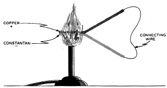
Fig. 24 - Using heat to produce a flow of electric current.
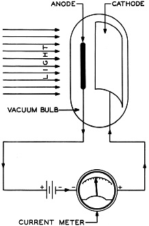
Fig. 25 - Using light to produce a flow of electric current.
Fig. 26 - An electric cell.
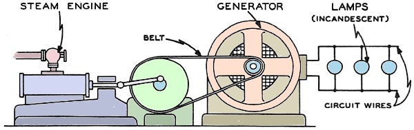
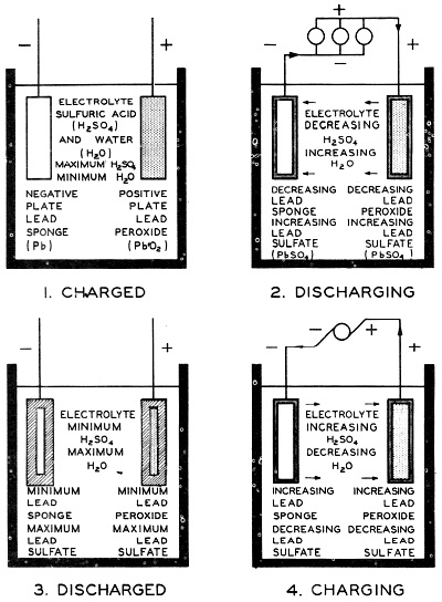
Fig. 27 - Components of a dry cell. At this point let's examine the several means of producing an emf. One of the most common ways is by mechanical power. In figure 22, the mechanical energy developed by the steam engine is transmitted to the electric generator by the belt. The electric generator generates an emf, which sets electrons in motion, and the moving electrons or current flow, in turn, causes the lamps to glow. Other mechanical means of generating electromotive force which you may be familiar with are the fan belt on your car which also drives the generator, the heavy Diesel-driven generators used as standby electrical supply, or the turbines which impel the generators of hydroelectric installations. Chemical action is the second most common method of producing an emf. The dry cell shown in figure 23 produces an emf by this method. The diagram shows an open circuit, but when the push button is pressed to make contact the circu1t closes and electrons flow through it, causing the bell to ring. A little farther on in this chapter we're going to take both a dry cell and a storage battery to pieces. Besides these two common methods, there are three others. One, the thermo-electric method, discovered in 1882, uses the principle that an electric current can be produced in a circuit made of two dissimilar metals if the points of contact are heated as shown in figure 24. The amount of current produced is quite small and is proportional to the difference in temperature between the unheated ends ad the junction (heated ends). Nevertheless, this principle has one important application on aircraft - in temperature-indicating devices called thermocouples, which make it possible for the pilot to know temperatures at critical points. In radial engines, for instance, thermocouples relay the cylinder head temperature to gages on the pilot's instrument panel. Photo-electric effect is another method used in industrial plants where a beam of light needs to be interrupted and in sound on film reproduction in motion picture systems. When light strikes certain surfaces, electrons are given off from the surface, creating a photo-electric effect. If you will look now at figure 25, you can see how this kind of cell works. If a beam of light enters this cell and falls on the sensitive surface, the cathode, electrons leave this surface and, being negative, travel toward the anode, positively charged with respect to the cathode. (A cathode tube can be assembled in several different ways. One common way is to coat the inside I of a glass tube with a mixture of silver, cesium, and cesium and silver oxides t o: form the cathode, and to use a center wire for the anode.) Note that the anode is connected to the positive terminal of the battery and that the cathode is connected through the meter to the negative. On the left hand lower side of the drawing, the symbol (//////) represents the battery, the long line on the left the positive terminal and the short line on the right the negative terminal. After striking the anode, the electrons then flow in the circuit toward the cathode and give an indication of current on the meter. Besides being used in factories and motion picture sound systems, the photoelectric cell is the basis of the photographer's exposure meter. The last process we're going to talk about is the piezo-electric production of an emf. If certain crystals, such as quartz and rochelle salt, are subjected to pressure, a potential difference will appear between the two points on opposite sides of the crystal to which pressure is being applied. So when a connecting wire is placed between the two points, a small current flows in the wire. The inverse of this occurrence is also striking. If you place a plate of piezoelectric material between metal electrodes and give the latter a difference of potential, the plate becomes thicker or thinner, depending upon which electrode is positive and which is negative. 49. The Principle of the Electric Cell Several paragraphs back we mentioned that chemical action is one of the most important ways we have of producing electric current. Let's look first at the chemical action of an electric cell. If two dissimilar metals, such as copper and zinc, are placed in a dilute acid solution, an electric cell will have been constructed that will generate an emf. If the copper and zinc strips, which are called electrodes, are connected by a wire as shown in figure 26, an electric current will flow through the conductor. The emf causing the current to flow is produced by chemical action between the electrodes and the acid solution. Although copper, zinc, and a solution of acid were used in the above example, any two dissimilar metals and a solution capable of conducting an electric current would form an electric cell. A solution which will conduct an electric current is called an electrolyte. The difference in emf's produced by different electric cells. 50. The Dry Cell The common dry cell is an every day example of producing a current by chemical means. We use it in all sorts of devices which need small amounts of current in short, irregular intervals - doorbells and flashlights for instance. Figure 27 sketches the construction of one, or better still, why don't you get an old flashlight battery and see what its insides look like? The positive electrode, or anode, of the dry cell is a carbon rod located in the center of a zinc container that forms the negative electrode, or cathode. A dilute solution of ammonium chloride - sal ammoniac - is mixed with some porous, inert material to form a paste, which is placed on the inside of the zinc container. Between this paste and the carbon rod is a porous mass of manganese dioxide and granulated carbon. What this mixture of manganese dioxide and granulated carbon does is to absorb the ammonia and. hydrogen gases given off when current is flowing through the cell. The function of this mixture which is called the depolarizer, is to fight off the accumulations of hydrogen gas at the positive electrode. This accumulation of hydrogen as the positive electrode is referred to as polarization and tends to reduce the amount of current the cell can furnish. The top of the cell is sealed by an insulating compound so that you can only see the terminals connected to the carbon rod and the zinc container. Cardboard surrounds the zinc container, acting as a protector and insulator. Each dry cell has an emf of 1.5 volts regardless of its physical size. The advantage of a large dry cell is that it lasts longer than a small one under the same conditions. A small cell however, can be carried more easily. Some dry cells, such as flashlight cells, are used individually. Some t i me s , often in fact, several dry cells are connected to increase the voltage, the current, or both. Any combination of cells is a battery. In your work with radar, you'll meet the B-battery, a combination of dry cells, in portable radar and radio equipment. 51. The Lead Acid Cell So much for the dry cell. Suppose we scan at this point the storage battery which everybody has seen in his car. The usual automobile storage battery is a combination of three lead-acid cells. The cell consists of a positive plate of lead peroxide and a negative plate of porous or spongy lead in a dilute solution of sulphuric acid. The usual construction of the lead-acid cell of this type is known as the pasted-grid construction, in which a lead and antimony alloy is' used to make a grid. This grid is filled with a paste, which, after a forming process, produces lead peroxide as the active chemical material. The grid acts as a physical support for the lead peroxide and as an electrical conductor for the current that is developed by chemical action. A similar grid is used for the negative plate; hut a different paste is used, which, after the forming process, consists mainly of pure lead in a very porous condition. The plates are supported in a hard rubber container holding a solution of sulphuric acid. The chemical reactions are too complicated for us to describe in detail. Essentially, though, here's what happens: insulating compound so that you can only We'll begin with discharge and assume that see the terminals connected to the carbon the cell is part of a closed circuit. Once the reactions have begun, electrons are deposited on the negative electrode. From there they flow by way of the circuit outside the battery to the positive electrode, thence through the solution back to the negative electrode.
Fig. 28 - Chemicals in action of the charge and discharge of a lead-acid storage battery. When the electrons flow in this direction the cell is discharging as in figure 28. But if we connect a d-c generator capable however, can be carried more easily. of generating a greater emf than the battery to the circuit in such a way as to make electrons flow from the negative electrode straight through the solution to the positive electrode, then the battery is charging. Or to say it simply, the direction of electron flow on discharge is opposite to its direction on charge. As a lead-acid cell discharges, the active materials in both plates change to lead sulphate. If the cell is allowed to discharge until all the active material in the plates has changed to lead sulphate, the cell is completely dead and will pro-duce no electromotive force. More often, however, a cell becomes sulphated to the extent that it will no longer produce the current required of it and must be charged. In your own automobile, you may have had to do this when you played the radio or ran the heater too much with the car parked. What you did was to prevent electrons from flowing from the negative to the positive electrode, a job which the generator does when you drive your car. When you do drive up to the corner service station and have your battery charged, an outside power source changes most of the lead sulphate back into the original active materials, and the cell is almost as good as new. Go back now to figure 28 showing the charging and discharging process, so you'll have this whole business tied down. If you're clear on this, let's pick up a little more "smart" about batteries. Each lead-acid cell, regardless of size, generates an emf of about 2.1 volts. The usual automobile battery is a 6-volt battery consisting of three lead-acid cells. It is rated at 6 volts instead of 6.3 volts (3 x 2.1 volts) because when in normal use only six volts are being applied to the external part of the circuit; the remaining 0.3 volt is being used to overcome the resistance to current f low inside. the battery. Called" internal resistance,'" this opposition is present in every cell and battery. The emf of the battery is the maximum voltage that it is capable of producing. The voltage available to operate an external circuit, called the terminal voltage of the battery, is the difference between the total emf and that part of the emf used to over-come the internal resistance of the battery. As more and more active. material in the plates is changed to lead sulphate, the internal resistance of the battery increases, causing more and more of the emf to be used within the battery and leaving less for use in the external circuit. Finally, a point is reached when the emf can no longer operate the circuit, as too great a part of it is used in over-coming the increased internal resistance. In other words, the terminal voltage has decreased below the value necessary for circuit operation. The battery must then be charged.
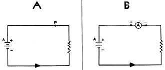
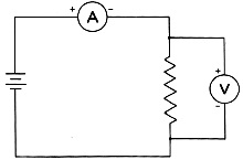
Fig. 29 - Use of the hydrometer to check the state of charge of a lead-acid storage battery. A device used with lead-acid cells to determine charge is the hydrometer. (See figure 29.) If the cell is fully charged, a given volume of the electrolyte is heavier than when the cell has a low charge or a high degree of sulphation. The float inside the tube will therefore rise higher when the battery is in a highly charged state than when the charge is low. 52. Rating of Storage Batteries If a lead-acid storage battery is connected in a circuit, the amount of current that flows in the circuit and, of course, through the battery is determined by the amount of resistance in the circuit. If the circuit has a large resistance, the amount of current will be correspondingly small; if the circuit has a small resistance, the amount of current will be correspondingly large. If the current is too large, the battery will become overheated, the internal resistance will rise, and the terminal voltage of the battery will fall below the amount required to operate the circuit. The maximum amount of current that can flow through the battery without causing overheating or excessive decrease in terminal voltage is the battery's current-carrying capacity which depends on the size of the plate area that is in direct contact with the electrolyte. If the plates are large, the current-carrying capacity of the battery will be larger than that of a battery with smaller plates. The unit on which a cell or battery is rated is the ampere-hour, numerically equal to the product of current flow in amperes and the time of flow in hours. For example, a 100 ampere-hour battery will provide a continuous current of 12.5 amperes for 8 hours. Theoretically, the same battery should 'provide a continuous current of 100 amperes for 1 hour; actually, however, the ampere-hour capacity decreases as the rate of discharge increases so that at the higher rate the capacity will fall ~below the 100 ampere-hour rating. The rating of a battery, fixed by the manufacturer, is a statement of the ampere-hours that a battery is capable of delivering continuously before the terminal voltage falls below a certain fixed minimum value. This minimum voltage differs somewhat with the type of cell and the rate of discharge. An automobile storage battery rated at 120 ampere-hours can be expected to deliver 20 amperes continuously for 6 hours. It will, however, deliver many times 20 amperes for a short period of time. In cold weather, it may be necessary for the battery to supply as much as 300 amperes for a short period of time to start an automobile. 53. Electrical Measuring Instruments Just as the grocer must have scales to weigh the tomatoes you buy from him, so does any electronics technician need instruments to measure various electrical quantities. We've told you some of the units by which we measure those quantities; now let's see what instruments we use to find out the number of units. Without knowing how to use instruments, you'd be just as bad off as a filling station attendant who just estimated how much gas he was putting in your car or a grocer who charged for tomatoes by guess. Generally, electrical instruments employ the magnetic effects of an electric current for their operation. Certainly you would expect to find an instrument to measure the amount of current in an electric circuit. The instrument used to do that is the ammeter, and it's connected in a circuit so that it will measure all the current passing a given point in the circuit. (See fig. 30.) Figure 30 (B) illustrates how an ammeter is connected in a circuit to measure the current passing the point P of figure 30(A). When a meter is connected in a circuit so that all the current that flows through the meter flows through the resistor, the meter is "in series" with the resistor. In figure 30(B) the ammeter is in series not only with the resistor but also with the battery.
Fig. 30 - Connecting an ammeter into an electrical circuit.
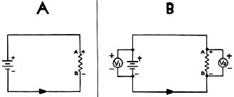
Fig. 31 - Connecting a voltmeter to read potential difference.
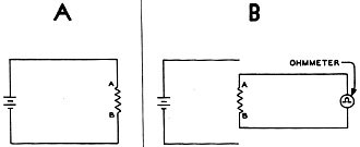
Fig. 32 - Using an ohmmeter to measure resistance.
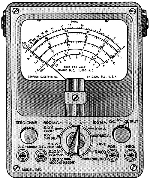
Fig. 33 - A typical multimeter.
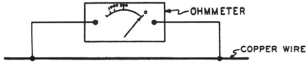
Fig. 34 - Measuring resistance between two points on a copper wire.
Fig. 35 - Measuring difference of potential along a copper wire. In connecting the ammeter, you have to observe polarity. To hook it up properly, trace electron flow from the negative side of the battery through the circuit and back to the positive side of the battery. Then you break the circuit and connect the ammeter so that electrons enter the negative terminal of the ammeter (clearly indicated on the instrument) and leave from the positive terminal, as in figure 30(B). We have some ammeters, by the way, which will measure quite small amounts of current. If an ammeter measures current in thousandths of an ampere, it's called a milliammeter; if it measures current in, millionths of an ampere, it's called a microammeter. Remember we talked about the centimeter-gram-second system of measurement way back there in section 32? Mighty important also to electronics workers is the voltmeter, which measures difference of potential or voltage. To measure the terminal voltage of a battery, you connect voltmeter V1 as shown in figure 31(B). Note that the positive terminal of the voltmeter is connected to the positive terminal of the battery and that the negative terminal of the voltmeter is connected to the negative terminal of the battery. To measure the potential difference between points A and B, you have to trace the electron flow and. observe the polarity of the two points. Note that the terminal of the resistor the electrons enter is designated the negative terminal. Meters connected across a difference of potential, like those in figure 31(B), are said to be connected in parallel. Another electrical measuring device you're likely to use quite a bit is the ohmmeter. What does it measure? Well, if you remember what an ohm is, and we hope you do, you've already deduced that the ohmmeter measures resistance in a circuit or any part of a c ir cui t. Figure 32 shows you how to connect one. In order to measure the resistance of the resistor AB, you disconnect the resistor from the rest of the circuit and connect the ohmmeter across it as shown in figure 32(B). Never attempt to measure the resistance of a resistor with an ohmmeter until you have disconnected it from the rest of the circuit. Nor do you need to observe polarity because a resistor has none except when connected in a circuit with current flowing in it. So that you can carry them around better, several electrical measuring devices may be combined in one case. If they are, the combination may be called a multimeter, a multitester, or a voltohmmeter. A common type of multimeter is illustrated in figure 33. 54. Some Approximations Used in Electricity Well, we're nearing the end of our chapter on the elements of electricity, so this is a good time to tell you that for convenience we make many statements about electricity that are practically true but which are inexact in the strict sense. We do this to simplify discussions about circuits and to solve problems more easily, especially practical ones. When the operation of the circuit is not affected unfavorably, we are justified in using approximations. For example, suppose we choose two points about one foot apart on a copper wire one-eighth inch in diameter. We would find, in using an ordinary ohmmeter (see fig. 34), the resistance between the two points to be zero. This is not correct, but the kind of ohmmeter used in ordinary work is not sensitive enough to indicate the very small resistance of this short length of wire. Consequently, when you see the diagram (schematic) of a circuit, you are to assume that the connecting lines representing the wires offer no resistance to the flow of current and that all resistance in the circuit is concentrated at the places in the diagram where the symbol for a resistor appears. If we place the copper wire of the above example in a circuit (see fig. 35) so that current flows in the wire and use a voltmeter to measure the difference of potential between the ends of the wire, the voltmeter will read zero even though there is a very small potential difference between the ends of the wire. The usual voltmeter is not sensitive enough to indicate this small difference of potential. When a circuit diagram is shown, you are to assume that between any two points of the diagram, separated only by a length of conducting wire, no difference of potential appears. In diagrams of circuits, all differences of potential are to be assumed as appearing only across resistors, batteries, generators, or other circuit elements. We will also assume in all problems and diagrams that the instruments are accurate and, for the present at least, that placing them in a circuit does not affect in any way the operation of the circuit, although it may to some degree in actual physical circuits. In most physical circuits, these approximations are permissible since our results are not appreciably affected by them. In circuits where we can't approximate, we will tell you so. 55. Electrically Identical Points Two points in a circuit, open or closed, are said to be electrically the same point if no difference of potential exists between them. On the other hand, if a difference of potential does exist between any two points, the points are not electrically the same. In figure 36, for instance, A, B, and C are electrically the same as are F, E, and D. C and D, though, are not. If we wish to measure the difference of potential across the resistor, here's what we do. We place the negative terminal of the voltmeter at either A, B, C, or any other point on the conductor between the negative terminal of the battery and the negative terminal of the resistor and place Fig. 36. Points which are electrically identical. the positive terminal of the voltmeter to any point on the conductor between the positive terminal of the battery and the positive terminal of the resistor. The results will be the same no matter where you place the terminals of the voltmeter as long as they are on the proper sides of the resistor. 56. Summary We're sure you'll admit that we've covered a lot of territory in this chapter. So about all we can do in the summary is to state very briefly some of the key ideas. If a definition doesn't seem absolutely clear to you, you should turn back through the text till you come to the full explanation. What follows just reminds you what you ought to know at this point. The centimeter-gram-second (C.G.S.) system of measurement is widely used by scientists to express the magnitude of physical quantities. The centimeter (cm) is a unit of length, the gram (g) is a unit of mass, and the second (see) is a unit of time. Mass, force, work, and energy are basic physical concepts used in all physical sciences. A unit of force is the dyne; units of work are ergs and joules; a unit of mass is the gram. Energy has the same units of measure as work since energy is the ability to do work. Power is the rate of doing work. In electricity, power is measured in watts. Matter is composed of elements and compounds which in turn are composed of atoms. In the interior of the atom is the nucleus, which is composed of protons and neutrons. A proton is a unit positive charge of electricity; the neutron has no electrical charge. Electrons, the smallest units of negative electricity, exist in orbits about the nucleus. The normal atom or molecule is electrically neutral, the negative charges of the electrons being exactly balanced by the positive charges of the equal number of protons. A body in its normal state is electrically neutral. Two bodies in their normal state will neither attract nor repel each other. A body is said to be charged negatively, with respect to its normal state, if it has acquired additional electrons. It is said to be charged positively, with respect to its normal state, if it has lost some of its normal number of electrons. Two bodies charged with the same kind of electricity will repel each other. If the bodies are charged with different kinds of electricity, they will attract each other. If two bodies, charged with different kinds of electricity or with different amounts of the same kind, are connected by a wire, electrons will flow in the wire. The body from which the electrons flow is said to be negative with respect to the body toward which they flow. Differently charged bodies are said to have a potential difference between them. An electric current is the flow of free electrons. The most common unit of current is the ampere, which is the flow of 6280 million billion electrons past a point in one second. The electric charge represented by 6280 million billion electrons is a coulomb of charge.
Fig. 37 - Standard Schematic symbols.
Table 1 - Common abbreviations and symbols. Electrons flow more readily through some materials than through others. In the increasing order of conductivity, such materials are classified as insulators, resistors, and conductors. The unit of electrical resistance is the ohm. Potential difference between two points in a circuit causes electrons to flow between them. The unit of potential difference is the volt, which is the electromotive force necessary to cause a current of one ampere to flow through a resistance of one ohm. Electricity may be produced by mechanical, chemical, thermal, photoelectric, or piezoelectric means. The most common methods are the chemical and mechanical ones. Meters are used for measuring various electrical quantities. The ammeter is used for measuring current and must always be connected in series with the device through which the current is to be measured. The voltmeter is used to measure emf and is connected in parallel with the device across which we wish to determine potential difference. The ohmmeter is used to measure resistance. It is necessary to remove the resistor from the circuit in order to measure its resistance with the ohmmeter. Electricity can be suitably harnessed to do work. Since it can do work, electricity possesses energy. The rate of doing work is power. Table 1 summarizes some common abbreviations, and figure 37 shows commonly used circuit symbols.
Review Questions The following questions are study aids. Your answers are not to be submitted to the USAF Extension Course Institute for grading. Correct answers will be found at the end of the text.
1. Is an electron matter? 2. Name three particles of an atom. Which particle has the least mass? 3. Is salt (sodium chloride) a mixture or a compound? Will the smallest particle of salt be an atom or a molecule? 4. Name two particles in the nucleus of an atom. 5. Indicate by means of arrows which way the electrically charged particles in figure 38 will move. 6. Compare the electric charge on the proton and electron: (a) as to quantity, (b) as to kind. 7. In what manner does a positively charged body differ from, a negatively charged body? 8. If the distance between two charges is doubled, what effect will it have on the force between the charges? 9. How much force exists tween two negative charges of 15 e.s.u. each if they are 3 cm. apart in air? 10. How much force exists between a positive charge of 36 e.s.u. and a negative charge of 24 e.s.u. if the charges are 4 cm. apart in air? 11. If figure 39 is not correct, correct it by redrawing. 12. Correct the drawing in figure 40 if it is not correctly drawn. 13. If figure 41 is not correct, correct it by redrawing. 14. What is an ion? 15. Current flow is the movement of __________ in a circuit. 16. Approximately how many electrons pass a given point in a conductor in one second if 3 amps of current are flowing in the circuit? 17. How many coulombs of electricity pass a given point in a conductor in one second if 10 amps of current are flowing in the conductor? 18. Which has the greatest number of free electrons per unit volume: conductors, resistors, or insulators? 19. What is the best metallic conductor of electricity? 20. What type of resistor is used in a circuit where the value of the resistance needs to be changed frequently? 21. How is polarity usually indicated? 22. The battery is an example of the production of electricity by what means? 23. What are the three principal effects of an electric current? 24. What are the values of the resistors shown in figure 42? 25. What is incorrect in figure 43? 26. How does an increase in the internal resistance of a battery affect the terminal voltage of the battery? 27. Theoretically, for how many hours should a one-hundred-ampere-hour battery be able to provide a continuous flow of current of five amperes? 28. What is an electrolyte? 29. What instrument is used to measure the condition of the electrolyte? 30. What does an ammeter measure? What principal effect of current is used in the operation of most meters? How should an ammeter be connected to measure the current through a resistor? 31. What does a voltmeter measure? How should a voltmeter be connected in a circuit to measure the potential difference existing across a 32. What instrument is u d to measure resistance? How is it used? 33. What instrument is used to measure resistance? How is it used? 34. What is power? In what unit is it measured in electricity? 35. Draw a circuit composed of a resistor connected across a battery showing an ammeter and a voltmeter so connected that the current through the resistor and the voltage drop across the resistor is measured. Use the symbols which have been presented in the discussion. 36. Match the following terms with the corresponding units: 37. Consider the resistor AB in figure 44. Electrons are flowing A toward B. Is A positive or negative with respect to B? 38. If an ammeter is properly connected at point C in the open circuit of figure 45, how much current will it indicate? 39. Each of the spheres in figure 46 is charged as shown. (a) Compare the polarity of each sphere with respect to each of the others. (b) In what direction would electrons flow if A and C were connected with a copper wire? (c) In what direction would electrons flow if Band C were so connected? (d) In what direction would electrons flow if A and B were so connected?
Review Question Answers
Fig. 47 - Answer to review question 5 of chapter 3.
Fig. 48 - Answer to review question 11 of chapter 3.
Fig. 49 - Answer to review question 12 of chapter 3.
Fig. 50 - Answer to review question 13 of chapter 3.
Fig. 51 - Answer to review question 35 of chapter 3. 1. No. Matter is composed of elements or physical and chemical combinations of elements. 2. Proton, neutron, electron. Electron. 3. Compound. Molecule. 4. Proton and neutron. 5. See figure 47. 6. (a) Same. (b) Opposite. 7. A positively charged body has been deprived of some of its normal number or electrons while a negatively charged body has an excess of electrons. 8. The force will be one-fourth the original force. 9. 25 dynes. 10. 54 dynes. 11. See figure 48. 12. See figure 49. 13. See figure 50. 14. An ion is an atom or molecule that has either been deprived of at least one electron or has gained at least one additional electron. 15. Electrons. 16. 3 x 6280 million billion electrons. 17. 10 coulombs. 18. Conductors. 19. Silver. 20. Variable resistor. 21. (-). (+). 22. Chemical. 23. Magnetic, heat, chemical. 24. A. 50 ohms ± 5%. B. 300 ohms ± 10%. 25. Figure indicates that the resistor is not within the tolerance range. 26. Causes a decrease In terminal voltage. 27. 20 hours. 28. Any solution that will conduct an electric current. 29. A hydrometer. 30. Current. Magnetic effect. In ser1es with the resistor. 31. Potential difference. In parallel with the resistor. 32. Ohmmeter. The resistor is removed from the circuit and the ohmmeter is connected across it. 33. A continuous path for current flow. An open circuit contains a break in the circuit so that current cannot flow in the circuit. 34. The rate of doing work. Watt. 35. See figure 51. 36. a. 3. b. 5. c. 1. d. 7. e. 2 37. A is negative with respect to B. 38. Zero. 39. (a) A is positive with respect to B, negative with respect to C.
Posted October 14, 2022 |