|
Fixed attenuators can be designed to have either equal or unequal impedances
and to provide any amount of attenuation (theoretically) equal to or greater than
the configuration's minimum attenuation - depending on the ratio of Z1/Z2.
Attenuators with equal terminations have a minimum attenuation of 0 dB. Unequal
terminations place a lower limit on the attenuation as follows:
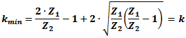 , for Z1 > Z2 in
circuits shown below , for Z1 > Z2 in
circuits shown below
Express
in decibels as: 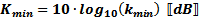
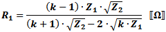
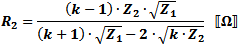
In the attenuator formulas below:
 , which is the linear
attenuation ratio of the two powers or voltages (note that
"k" has a minimum value if Z1 and Z2.are not equal). , which is the linear
attenuation ratio of the two powers or voltages (note that
"k" has a minimum value if Z1 and Z2.are not equal).
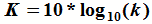
If, as is typical, the attenuation is given in decibels (K dB vs. k), then convert to a ratio as follows:
 <———>
<———>

|
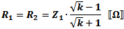
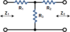
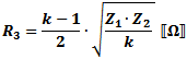
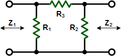
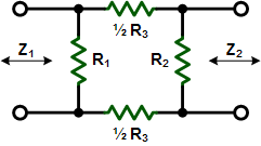
These equations apply to
the two forms of Tee attenuators at the left.
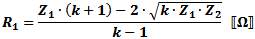
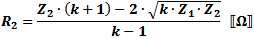
If Z1 = Z2, then:
|
 |
 |
|
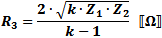
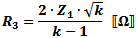
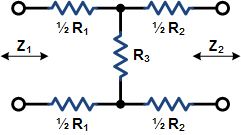
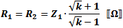
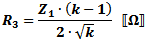
These equations apply to
the two forms of Pi attenuators at the left.
If Z1 = Z2, then:
|
 |
 |
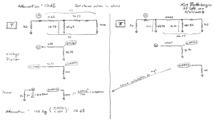
An RF Cafe visitor wrote to say that he thought the above equations might be
in error when unequal source and load termination resistances are used. The image
below shows the mathematical steps that prove the equations are correct. It uses
a source resistance of 50 ohms and a load resistance of 100 ohms, with an attenuation
of 10 dB. Resistor values for both the "T" and ""Pi" attenuators were determined
using the attenuator
calculator on RF Cafe (which uses these equations).
|


