Module 10 - Introduction to Wave Propagation, Transmission Lines, and Antennas
Navy Electricity and Electronics Training Series (NEETS) |
||||||||||||||||||||||||||||||||||||||||||||||||||
|
Module 10 − Introduction to Wave Propagation, Transmission Lines, and Antennas
Pages i, 1−1, 1−11, 1−21, 1−31, 1−41, 2−1, 2−11, 2−21, 2−31, 2−40, 3−1, 3−11, 3−21, 3−31, 3−41, 3−51, 4−1, 4−11, 4−21, 4−31, 4−41, 4−51, Index
an important factor to be considered when any two elements are parallel and are spaced so that considerable coupling is between them. There is very little mutual impedance between collinear sections. Where impedance does exist, it is caused by the coupling between the ends of adjacent elements. Placing the ends of elements close together is frequently necessary because of construction problems, especially where long lengths of wire are involved.
The effects of spacing and the advantages of proper spacing can be demonstrated by some practical examples. a collinear array consisting of two half-wave elements with 1/4-wavelength spacing between centers has a gain of 1.8 dB. If the ends of these same dipoles are separated so that the distance from center to center is 3/4 wavelengths and they are driven from the same source, the gain increases to approximately 2.9 dB.
A three-dipole array with negligible spacing between elements gives a gain of 3.3 dB. In other words, when two elements are used with wider spacing, the gain obtained is approximately equal to the gain obtainable from three elements with close spacing. The spacing of this array permits simpler construction, since only two dipoles are used. It also allows the antenna to occupy less space. Construction problems usually dictate small-array spacing.
Broadside Arrays
A broadside array is shown in figure 4-26, view A. Physically, it looks somewhat like a ladder. When the array and the elements in it are polarized horizontally, it looks like an upright ladder. When the array is polarized vertically, it looks like a ladder lying on one side (view B). View C is an illustration of the radiation pattern of a broadside array. Horizontally polarized arrays using more than two elements are not common. This is because the requirement that the bottom of the array be a significant distance above the earth presents construction problems. Compared with collinear arrays, broadside arrays tune sharply, but lose efficiency rapidly when not operated on the frequencies for which they are designed.
Figure 4-26. - Typical broadside array.
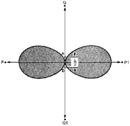
Radiation Pattern. - Figure 4-27 shows an end view of two parallel half-wave antennas (A and B) operating in the same phase and located 1/2 wavelength apart. At a point (P) far removed from the antennas, the antennas appear as a single point. Energy radiating toward P from antenna a starts out in phase with the energy radiating from antenna B in the same direction. Propagation from each antenna travels over the same distance to point P, arriving there in phase. The antennas reinforce each other in this direction, making a strong signal available at P. Field strength measured at P is greater than it would be if the total power supplied to both antennas had been fed to a single dipole. Radiation toward point P1 is built up in the same manner.
4-31
Figure 4-27. - Parallel elements in phase.
Next consider a wavefront traveling toward point Q from antenna B. By the time it reaches antenna A, 1/2 wavelength away, 1/2 cycle has elapsed. Therefore energy from antenna B meets the energy from antenna a 180 degrees out of phase. As a result, the energy moving toward point Q from the two sources cancels. In a like manner, radiation from antenna a traveling toward point Q1 meets and cancels the radiation in the same direction from antenna B. As a result, little propagation takes place in either direction along the QQ1 axis. Most of the energy is concentrated in both directions along the PP1 axis. When both antenna elements are fed from the same source, the result is the basic broadside array.
When more than two elements are used in a broadside arrangement, they are all parallel and in the same plane, as shown in figure 4-26, view B. Current phase, indicated by the arrows, must be the same for all elements. The radiation pattern shown in figure 4-26, view C, is always bi-directional. This pattern is sharper than the one shown in figure 4-27 because of the additional two elements. Directivity and gain depend on the number of elements and the spacing between them.
Gain and DirectIVITY. - The physical disposition of dipoles operated broadside to each other allows for much greater coupling between them than can occur between collinear elements. Moving the parallel antenna elements closer together or farther apart affects the actual impedance of the entire array and the overall radiation resistance as well. As the spacing between broadside elements increases, the effect on the radiation pattern is a sharpening of the major lobes. When the array consists of only two dipoles spaced exactly 1/2 wavelength apart, no minor lobes are generated at all. Increasing the distance between the elements beyond that point, however, tends to throw off the phase relationship between the original current in one element and the current induced in it by the other element. The result is that, although the major lobes are sharpened, minor lobes are introduced, even with two elements. These, however, are not large enough to be of concern.
If you add the same number of elements to both a broadside array and a collinear array, the gain of the broadside array will be greater. Reduced radiation resistance resulting from the efficient coupling between dipoles accounts for most of this gain. However, certain practical factors limit the number of
4-32 elements that may be used. The construction problem increases with the number of elements, especially when they are polarized horizontally.
Q32. What is the primary cause of broadside arrays losing efficiency when not operating at their designed frequency?
Q33. When more than two elements are used in a broadside array, how are the elements arranged?
Q34. As the spacing between elements in a broadside array increases, what is the effect on the major lobes?
End-Fire Arrays
An end-fire array looks similar to a broadside array. The ladder-like appearance is characteristic of both (fig. 4-28, view A). The currents in the elements of the end-fire array, however, are usually 180 degrees out of phase with each other as indicated by the arrows. The construction of the end-fire array is like that of a ladder lying on its side (elements horizontal). The dipoles in an end-fire array are closer together (1/8-wavelength to 1/4 -wavelength spacing) than they are for a broadside array.
Figure 4-28. - Typical end-fire array.
Closer spacing between elements permits compactness of construction. For this reason an end-fire array is preferred to other arrays when high gain or sharp directivity is desired in a confined space. However, the close coupling creates certain disadvantages. Radiation resistance is extremely low, sometimes as low as 10 ohms, making antenna losses greater. The end-fire array is confined to a single frequency. With changes in climatic or atmospheric conditions, the danger of detuning exists.
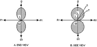
Radiation Pattern. - The radiation pattern for a pair of parallel half-wave elements fed 180 degrees out of phase is shown in figure 4-29, view A. The elements shown are spaced 1/2 wavelength apart. In practice, smaller spacings are used. Radiation from elements L and M traveling toward point P begins 180 degrees out of phase. Moving the same distance over approximately parallel paths, the respective wavefronts from these elements remain 180 degrees out of phase. In other words, maximum cancellation takes place in the direction of P. The same condition is true for the opposite direction (toward P1). The P to P1 axis is the line of least radiation for the end-fire array.
4-33
Figure 4-29. - Parallel elements 180 degrees out of phase.
Consider what happens along the QQ1 axis. Energy radiating from element M toward Q reaches element L in about 1/2 cycle (180 degrees) after it leaves its source. Since element L was fed 180 degrees out of phase with element M, the wavefronts are now in the same phase and are both moving toward Q reinforcing each other. Similar reinforcement occurs along the same axis toward Q1. This simultaneous movement towards Q and Q1 develops a bi-directional pattern. This is not always true in end-fire operation. Another application of the end-fire principle is one in which the elements are spaced 1/4 wavelength apart and phased 90 degrees from each other to produce a unidirectional pattern. In figure 4-29, view A, elements a and B are perpendicular to the plane represented by the page; therefore, only the ends of the antennas appear. In view B the antennas are rotated a quarter of a circle in space around the QQ1 axis so that they are seen in the plane of the elements themselves. Therefore, the PP1 axis, now perpendicular to the page, is not seen as a line. The RR1 axis, now seen as a line, is perpendicular to the PP1 axis as well as to the QQ1 axis. The end-fire array is directional in this plane also, although not quite as sharply. The reason for the greater broadness of the lobes can be seen by following the path of energy radiating from the midpoint of element B toward point S in view B. This energy passes the a element at one end after traveling slightly more than the perpendicular distance between the dipoles. Energy, therefore, does not combine in exact phase toward point S. Although maximum radiation cannot take place in this direction, energy from the two sources combines closely enough in phase to produce considerable reinforcement. a similar situation exists for wavefronts traveling toward T. However, the wider angle from Q to T produces a greater phase difference and results in a decrease in the strength of the combined wave.
Directivity occurs from either one or both ends of the end-fire array, along the axis of the array, as shown by the broken arrows in figure 4-28, view A; hence, the term end-fire is used.
The major lobe or lobes occur along the axis of the array. The pattern is sharper in the plane that is at right angles to the plane containing the elements (figure 4-29, view A). If the elements are not exact half-wave dipoles, operation is not significantly affected. However, because of the required balance of phase relationships and critical feeding, the array must be symmetrical. Folded dipoles, such as the one shown in figure 4-20, view A, are used frequently because the impedance at their terminals is higher. This is an effective way of avoiding excessive antenna losses. Another expedient to reduce losses is the use of tubular elements of wide diameter.
Gain and DirectIVITY. - In end-fire arrays, directivity increases with the addition of more elements and with spacings approaching the optimum. The directive pattern for a two-element,
4-34 bi-directional system is illustrated in figure 4-29. View a shows radiation along the array axis in a plane perpendicular to the dipoles, and view B shows radiation along the array axis in the plane of the elements. These patterns were developed with a 180-degree phase difference between the elements. Additional elements introduce small, minor lobes.
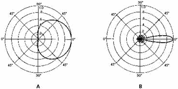
With a 90-degree phase difference in the energy fed to a pair of end-fire elements spaced approximately 1/4 wavelength apart, unidirectional radiation can be obtained. The pattern perpendicular to the plane of the two elements is shown in figure 4-30, view A. The pattern shown in view B, taken in the same plane, is for a six-element array with 90-degree phasing between adjacent elements. Since both patterns show relative gain only, the increase in gain produced by the six-element array is not evident. End-fire arrays are the only unidirectional arrays wholly made up of driven elements.
Figure 4-30. - Unidirectional end-fire arrays.
Q35. What are some disadvantages of the end-fire array?
Q36. Where does the major lobe in the end-fire array occur?
Q37. To maintain the required balance of phase relationships and critical feeding, how must the end-fire array be constructed?
Parasitic Arrays
If a small light bulb were placed in the center of a large room, the illumination would be very poor. However, if a reflector were placed behind the bulb, the space in front of the reflector would be brighter and the space behind the reflector would be dimmer. The light rays would be concentrated. Also, if a lens were placed in front of the bulb, the light would be even more concentrated and a very bright spot would appear on the wall in front of the lens. a flashlight is a practical combination of the small bulb, the reflector, and the lens. The energy from an antenna can be reflected and concentrated in a similar manner.
Although we do not usually discuss the gain of a flashlight, we can continue the comparison of an antenna and a flashlight to explain the meaning of antenna gain. Suppose the spot on the wall in front of the flashlight becomes 10 times brighter than it was when only the open bulb was used. The lens and reflector have then produced a 10-fold gain in light. For antennas, the simple half-wave antenna corresponds to the open bulb in the flashlight. Suppose an antenna system concentrates the radio waves so
4-35 that at a particular point the field strength is 10 times more than it would be at the same distance from a half-wave antenna. The antenna system is then said to have a gain of 10.
Parasitic arrays represent another method of achieving high antenna gains. a parasitic array consists of one or more parasitic elements placed in parallel with each other and, in most cases, at the same line-of-sight level. The parasitic element is fed inductively by radiated energy coming from the driven element connected to the transmitter. It is in NO way connected directly to the driven element.
When the parasitic element is placed so that it radiates away from the driven element, the element is a director. When the parasitic element is placed so that it radiates toward the driven element, the parasitic element is a reflector.
The directivity pattern resulting from the action of parasitic elements depends on two factors. These are (1) the tuning, determined by the length of the parasitic element; and (2) the spacing between the parasitic and driven elements. To a lesser degree, it also depends on the diameter of the parasitic element, since diameter has an effect on tuning.
Operation. - When a parasitic element is placed a fraction of a wavelength away from the driven element and is of approximately resonant length, it will re-radiate the energy it intercepts. The parasitic element is effectively a tuned circuit coupled to the driven element, much as the two windings of a transformer are coupled together. The radiated energy from the driven element causes a voltage to be developed in the parasitic element, which, in turn, sets up a magnetic field. This magnetic field extends over to the driven element, which then has a voltage induced in it. The magnitude and phase of the induced voltage depend on the length of the parasitic element and the spacing between the elements. In actual practice the length and spacing are arranged so that the phase and magnitude of the induced voltage cause a unidirectional, horizontal-radiation pattern and an increase in gain.
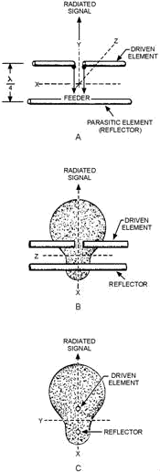
In the parasitic array in figure 4-31, view A, the parasitic and driven elements are spaced 1/4 wavelength apart. The radiated signal coming from the driven element strikes the parasitic element after 1/4 cycle. The voltage developed in the parasitic element is 180 degrees out of phase with that of the driven element. This is because of the distance traveled (90 degrees) and because the induced current lags the inducing flux by 90 degrees (90 + 90 = 180 degrees). The magnetic field set up by the parasitic element induces a voltage in the driven element 1/4 cycle later because the spacing between the elements is 1/4 wavelength. This induced voltage is in phase with that in the driven element and causes an increase in radiation in the direction indicated in figure 4-31, view A. Since the direction of the radiated energy is stronger in the direction away from the parasitic element (toward the driven element), the parasitic element is called a reflector. The radiation pattern as it would appear if you were looking down on the antenna is shown in view B. The pattern as it would look if viewed from the ends of the elements is shown in view C.
4-36
Figure 4-31. - Patterns obtained using a reflector with proper spacing.
Because the voltage induced in the reflector is 180 degrees out of phase with the signal produced at the driven element, a reduction in signal strength exists behind the reflector. Since the magnitude of an induced voltage never quite equals that of the inducing voltage, even in very closely coupled circuits, the energy behind the reflector (minor lobe) is not reduced to 0.
The spacing between the reflector and the driven element can be reduced to about 15 percent of a wavelength. The parasitic element must be made electrically inductive before it will act as a reflector. If
4-37 this element is made about 5 percent longer than 1/2 wavelength, it will act as a reflector when the spacing is 15 percent of a wavelength.
Changing the spacing and length can change the radiation pattern so that maximum radiation is on the same side of the driven element as the parasitic element. In this instance the parasitic element is called a director.
Combining a reflector and a director with the driven element causes a decrease in back radiation and an increase in directivity. This combination results in the two main advantages of a parasitic array - unidirectivity and increased gain. If the parasitic array is rotated, it can pick up or transmit in different directions because of the reduction of transmitted energy in all but the desired direction. An antenna of this type is called a ROTARY ARRAY. Size for size, both the gain and directivity of parasitic arrays are greater than those of driven arrays. The disadvantage of parasitic arrays is that their adjustment is critical and they do not operate over a wide frequency range.
Gain and DirectIVITY. - Changing the spacing between either the director or the reflector and the driven element results in a change in the radiation pattern. More gain and directivity are obtained by changing the length of the parasitic elements.
The FRONT-to-BACK RATIO of an array is the proportion of energy radiated in the principal direction of radiation to the energy radiated in the opposite direction. a high front-to-back ratio is desirable because this means that a minimum amount of energy is radiated in the undesired direction. Since completely suppressing all such radiation is impossible, an infinite ratio cannot be achieved. In actual practice, however, rather high values can be attained. Usually the length and spacing of the parasitic elements are adjusted so that a maximum front-to-back ratio is obtained, rather than maximum gain in the desired direction.
Q38. What two factors determine the directivity pattern of the parasitic array?
Q39. What two main advantages of a parasitic array can be obtained by combining a reflector and a director with the driven element?
Q40. The parasitic array can be rotated to receive or transmit in different directions. What is the name given to such an antenna?
Q41. What are the disadvantages of the parasitic array?
Multielement Parasitic Array
A MULTIELEMENT PARASITIC array is one that contains two or more parasitic elements with the driven element. If the array contains two parasitic elements (a reflector and a director) in addition to the driven element, it is usually known as a THREE-ELEMENT ARRAY. If three parasitic elements are used, the array is known as a FOUR-ELEMENT ARRAY, and so on. Generally speaking, if more parasitic elements are added to a three-element array, each added element is a director. The field behind a reflector is so small that additional reflectors would have little effect on the overall radiation pattern. In radar, from one to five directors are used.
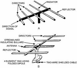
CONSTRUCTION. - The parasitic elements of a multi-element parasitic array usually are positioned as shown in figure 4-32, views a and B. Proper spacings and lengths are determined experimentally. a folded dipole (view B) is often used as the driven element to obtain greater values of radiation resistance.
4-38
Figure 4-32. - Yagi antenna.
YAGI Antennas. - An example of a multielement parasitic array is the YAGI Antenna (figure 4-32, views a and B). The spacings between the elements are not uniform. The radiation from the different elements arrives in phase in the forward direction, but out of phase by various amounts in the other directions.
The director and the reflector in the Yagi antenna are usually welded to a conducting rod or tube at their centers. This support does not interfere with the operation of the antenna. Since the driven element is center-fed, it is not welded to the supporting rod. The center impedance can be increased by using a folded dipole as the driven element.
The Yagi antenna shown in figure 4-32, view A, has three directors. In general, the greater number of parasitic elements used, the greater the gain. However, a greater number of such elements causes the array to have a narrower frequency response as well as a narrower beamwidth. Therefore, proper adjustment of the antenna is critical. The gain does not increase directly with the number of elements used. For example, a three-element Yagi array has a relative power gain of 5 dB. Adding another director results in a 2 dB increase. Additional directors have less and less effect.
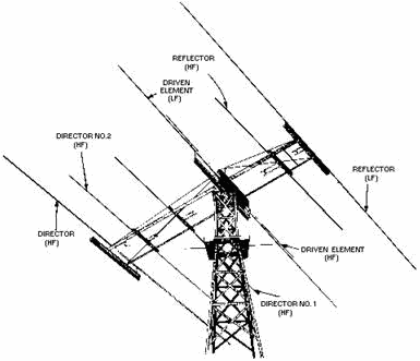
a typical Yagi array used for receiving and transmitting energy is shown with a support frame in figure 4-33. This antenna is used by the military services. It operates at frequencies of from 12 to 50 megahertz and consists of two separate arrays (one high-frequency and one low-frequency antenna array) mounted on one frame. The various elements are indicated in the figure. The high-frequency (hf) array consists of one reflector, one driven element, and two directors; the low-frequency (lf) array has the same arrangement with one less director. The lengths of the elements in the high-frequency array are shorter than those in the low-frequency array. The physical lengths of the elements in the individual arrays are equal, but the electrical lengths can be varied by means of the tuning stubs at the center of the elements. The array can be rotated in any desired direction by a remotely controlled, electrically driven, antenna rotator.
4-39
Figure 4-33. - a typical parasitic array used for transmitting and receiving.
Q42. What is the advantage of adding parasitic elements to a Yagi array?
Q43. The Yagi antenna is an example of what type of array?
Special Antennas
In this section we will cover some special communications and radar antennas. Some of these antennas we touch on briefly since they are covered thoroughly in other courses.
Previously discussed antennas operate with standing waves of current and voltage along the wires. This section deals principally with antenna systems in which the current is practically uniform in all parts of the antenna. In its basic form, such an antenna consists of a single wire grounded at the far end through a resistor. The resistor has a value equal to the characteristic impedance of the antenna. This termination, just as in the case of an ordinary transmission line, eliminates standing waves. The current, therefore, decreases uniformly along the wire as the terminated end is approached. This decrease is caused by the loss of energy through radiation. The energy remaining at the end of the antenna is dissipated in the terminating resistor. For such an antenna to be a good radiator, its length must be fairly long. Also, the wire must not be too close to the ground. The return path through the ground will cause cancellation of the radiation. If the wire is sufficiently long, it will be practically nonresonant over a wide range of operating frequencies.
4-40
|
||||||||||||||||||||||||||||||||||||||||||||||||||

