Navy Electricity and Electronics Training Series (NEETS) |
||||||||||||||||||||||||||||||||||||||||||||||||||
|
Module 10 − Introduction to Wave Propagation, Transmission Lines, and Antennas
Pages i, 1−1, 1−11, 1−21, 1−31, 1−41, 2−1, 2−11, 2−21, 2−31, 2−40, 3−1, 3−11, 3−21, 3−31, 3−41, 3−51, 4−1, 4−11, 4−21, 4−31, 4−41, 4−51, Index
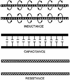
LEAKAGE CURRENT flows between the wires of a transmission line through the dielectric. The dielectric acts as a resistor.
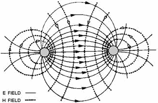
An ELECTROMagnetic FIELD exists along transmission line when current flows through it.
3-51
Characteristic Impedance, Z0, is the ratio of E to I at every point along the line. For maximum transfer of electrical power, the characteristic impedance and load impedance must be matched.
The VELOCITY at which a wave travels over a given length of transmission line can be found by using the formula:
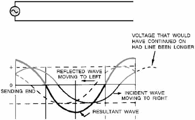
A transmission line that is not terminated in its characteristic impedance is said to be FINITE. When dc is applied to an OPEN-ENDED line, the voltage is reflected back from the open end without any change in polarity, amplitude, or shape. Current is reflected back with the same amplitude and shape but with opposite polarity.
3-52 When dc is applied to a Short-CircuitED line, the current is reflected back with the same amplitude, and polarity. The voltage is reflected back with the same amplitude but with opposite polarity.
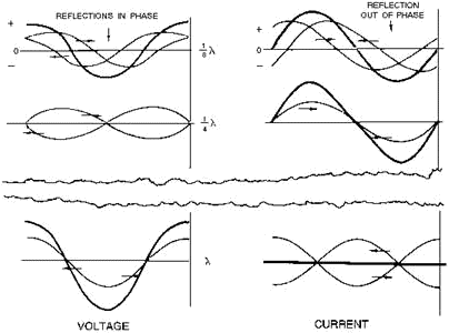
When ac is applied to an OPEN-END line, voltage is always reflected back in phase with the incident wave and current is reflected back out of phase.
When ac is applied to a Short-CircuitED line, voltage is reflected in opposite phase, while current is reflected in phase.
3-53
A NONRESONANT line has NO Standing WAVES of current and voltage and is either infinitely long or terminated in its characteristic impedance.
A RESONANT line has Standing WAVES of current and voltage and is of finite length and is NOT terminated in its characteristic impedance.
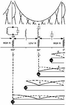
On an open-ended resonant line, and at all odd 1/4λ points, the voltage is minimum, the current is maximum, and the impedance is minimum. At all even 1/4λ points, the voltage is maximum, the current is minimum and the impedance is maximum.
3-54
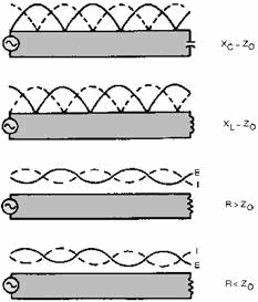
There are a variety of TERMINATIONS for RF lines. Each termination has an effect on the standing waves on the line.
3-55
A transmission line can be terminated in its characteristic impedance as an open- or short-circuit, or in capacitance or inductance.
Whenever the termination on a transmission line is NOT EQUAL to Z0, there are reflections on the line. The amount of voltage reflected may be found by using the equation:
When the termination on a transmission line EQUALS Z0, there is NO reflected voltage.
The measurement of standing waves on a transmission line yields information about operating conditions. If there are NO standing waves, the termination for that line is correct and maximum power transfer takes place.
The Standing WAVE RATIO is the measurement of maximum voltage (current) to minimum voltage (current) on a transmission line and measures the perfection of the termination of the line. a ratio of 1:1 describes a line terminated in its characteristic impedance.
3-56 Answers to Questions Q1. Through Q30.
A1. Transmission line.
A2. Input end, generator end, transmitter end, sending end, and source.
A3. Output end, receiving end, load end and sink.
A4. Parallel two-wire, twisted pair, shielded pair, coaxial line and waveguide.
A5. Power lines, rural telephone lines, and telegraph lines.
A6. High radiation losses and noise pickup.
A7. Twin lead.
A8. The conductors are balanced to ground.
A9. Air coaxial (rigid) and solid coaxial (flexible).
A10. The ability to minimize radiation losses.
A11. Expensive to construct, must be kept dry, and high frequency losses limit the practical length of the line.
A12. Cylindrical and rectangular.
A13. Copper, dielectric, and radiation.
A14. Copper losses.
A15. Dielectric losses.
A16. PHWHUV
A17. (1) Type of line used, (2) dielectric in the line, and (3) length of line.
A18. Inductance is expressed in microhenrys per unit length, capacitance is expressed in picofarads per unit length, and resistance is expressed in ohms per unit length.
A19. The small amount of current that flows through the dielectric between two wires of a transmission line and is expressed in micromhos per unit length.
A20. When the characteristic impedance of the transmission line and the load impedance are equal.
A21. Z0 and it is the ratio of E to I at every point along the line.
A22. Between 50 and 600 ohms.
A23. Incident waves from generator to load. Reflected waves from load back to generator.
A24. 2 and 6 have zero resultant wave and they indicate that the incident and reflected waves are 180 degrees out of phase at all parts.
A25. One-fourth the distance from each end of the line.
3-57 A26. The load impedance of such a line is equal to Z0.
A27. Even quarter-wave points (1/2λ, 1λ, 3/2λ, etc.).
A28. At 1/2 wavelength from the end and at every 1/2 wavelength along the line.
A29. Power standing-wave ratio (pswr).
A30. The existence of voltage variations on a line.
3-58
|
||||||||||||||||||||||||||||||||||||||||||||||||||
