|
Electricity - Basic Navy Training Courses NAVPERS 10622 |
|
Here is the "Electricity - Basic Navy Training Courses" (NAVPERS 10622) in its entirety. It should provide one of the Internet's best resources for people seeking a basic electricity course - complete with examples worked out. See copyright. See Table of Contents.
¶ U.S. GOVERNMENT PRINTING OFFICE; 1945 - 618779
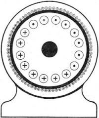
CHAPTER 21 Many electrical devices and machines operate on the principle of TRANSFORMER ACTION. THEY ARE NOT TRANSFORMERS - but the theory of their operation is best explained by considering them AS IF THEY WERE TRANSFORMERS. This term "transformer action" comes from the current and voltage relationships in a transformer. Bound up in the term are a number of separate meanings. Each one is important and each one finds application in special electrical equipment. If you thoroughly understand "transformer action" you can understand more than half of all the electrical machinery built. Let's take each item in the general term "transformer action" and analyze it. POWER TRANSFER Power transfer means that the device has TWO circuits. The power is fed into one circuit and is transferred to the other by magnetic induction. This means that you are always dealing with a magnetic circuit. And you'll run in to lots of iron to preserve this magnetism. Whenever you see TWO, circuits in a machine, one of them having no connection to the power source, you can be pretty sure that transformer action makes the machine run. VOLTAGE CHANGES Voltage changes usually take place whenever you have transformer action. Check your primary and secondary circuits for differences in the number of conductors. If the number of conductors goes up - you can count on the voltage going up. Then too - check for movement between your primary and secondary. If one moves in relation to the other, more flux is going to be cut-you can count on the secondary voltage being higher than if there was no relative movement. CURRENT CHANGES Remember that you do not get something for nothing. If the secondary voltage goes up, there will be an increase in secondary current. Since secondary current controls primary input, you can be sure that primary current goes up too. The powers of the primary and secondary will always be equal (neglecting losses). Whatever is TAKEN OUT in increased voltage and current must be paid for by increased current INPUT. CIRCUIT POLARITY THEY'RE ALWAYS OPPOSITE. The two currents - primary and secondary - are always flowing in opposite directions. This means that the magnetic poles produced in the two circuits are always opposite to each other. THREE VOLTAGES In transformer action you'll always find three voltages to consider. First there is the applied voltage from the source. This is the primary voltage or Ep. Second, there is the voltage of self-induction on the primary. It's produced by the primary's own field - Esi. Third, there is the induced voltage in the secondary - the Es (this Es is produced by the primary field) Esi and Es are alike in direction but both are opposite to the Ep. FREQUENCY If there is no relative movement between primary and secondary, frequencies are equal. But, if there is MOVEMENT, the NUMBER of cuttings received by the secondary depends on both PRIMARY FREQUENCY and the RELATIVE SPEED OF MOVEMENT. With relative motion the frequency of the secondary either goes up or down. FINAL CONTROL The AMOUNT of current, EVERYWHERE, in transformer action, is controlled by conditions in the secondary. Watch what happens to the current in the secondary - that's the key to what goes on in the primary. Don't forget that Esi has the primary current almost choked off. It's up to the secondary field to reduce the Esi and permit current to flow in the primary. INDUCTION MOTORS Induction motors certainly don't look like transformers. But let's CONSIDER a three-phase squirrel cage motor as a transformer. The one in figure 226 is a good example. It is shown in a cross-sectional view. You must consider the stator as the primary - it's connected to the source. And the rotor as the secondary - its power comes from the field of the primary. First, how about the two voltages? Well, is it a step-down or step-up? Step-down - because the secondary (rotor) has fewer turns than the primary (stator). What do you think would happen if this was reversed? Imagine a rotor with more turns than the stator - a step-up job. The rotor, being short circuited by its end rings, would have a tremendous current. So would the stator - it's controlled by rotor current. This job would cook in short order! And that is exactly why squirrel cage rotors have fewer turns than their stators. The designer not only understood transformer action, but he made use of it.
Figure 226. - lnduction motor as a transformer. Why does the rotor turn? Because it's a secondary, and its poles are opposite to those of the primary. Attraction between primary and secondary produces torque, and torque produces rotation. Why does a large induction motor have to be protected against high starting current? Because, at the start, the rotating field (primary) is cutting the rotor (secondary) at a furious rate. Extremely high voltages are induced in the secondary - high current flows. The primary, subject to secondary control, likewise carries a high current. If this high primary current wasn't cut down by a starter, the primary would go up in smoke. All right - then why isn't a starting resistance needed when the motor is running? Because when the secondary is revolving WITH the primary field there is less relative motion between them. Less flux is cut - secondary voltage and current is less - and likewise the primary current is reduced to a safe value.
It's interesting to imagine what the conditions would be IF the rotor ever caught up to the stator field. This would mean that each rotor conductor would ride right along with the flux of the rotating field. No relative motion! No flux cut. No Es. No current in the motor. No torque! Which tells you that an induction rotor can NEVER rotate as fast as the stator's magnetic field. How about the rotor frequency? When the rotor is standing still (at startup), it is cut by every pulse of the stator's a-c field. Rotor and stator frequencies are the same. But as the rotor picks up speed, it rides WITH the field. There is less and less relative motion and the rotor frequency becomes lower and lower.
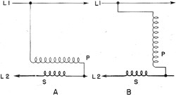
These are the most important facts about a squirrel cage motor. The engineer designs the motor on the oasis of these facts. And all of them can be understood by simply considering the motor as a transformer. The wound-rotor induction motor can be considered the same as the squirrel cage. Both motors operate on the same principle. INDUCTION REGULATORS INDUCTION REGULATORS are transformer devices used to regulate the voltage in a-c lines. Figure 227 shows a schematic of a regulator and its connection in a line. The primary winding is mounted on a movable cylindrical iron core and connected ACROSS the line. The secondary is wound in slots on a stationary core surrounding the primary. It is connected IN the line. The secondary is connected so that its voltage will add to the line to offset line drop. The machine looks like a motor but it is used as a transformer. The primary has a line current and establishes a field around the movable core. When the primary is in position A, all its flux cuts the secondary. This induces voltage in the secondary which adds to the line voltage (line and secondary are in series). But when the primary is in position B, its flux does not cut the secondary. No voltage is added to the line. Changing the primary position alters the amount of flux which cuts the secondary. More or less voltage is induced in the secondary depending on the primary position. In this way, the line can have any voltage added to it that is necessary.
Figure 227. - lnduction regulator. This is a much better method of voltage regulation than the use of a rheostat. Rheostats consume power in their resistance. The power is wasted as heat. But the induction regulator delivers back just about as much power as it consumes. When it is in the zero position, B, the Esi reduces current in the primary almost to zero. Therefore, there is only a slight loss whether the regulator is boosting the voltage or is turned completely off. These devices are built for either automatic or hand operation. FREQUENCY CONVERTER Usually a.c. is generated at a frequency of 60 cycles. But a higher frequency is required for some high speed motors, radio circuits, and heating devices. One of the easiest ways of producing this higher frequency is by means of a FREQUENCY CONVERTER. Frequency converters are built like wound-rotor motors. The primary is the stator and the secondary is the rotor. The secondary voltage is taken off the rotor by slip rings. With the secondary standing still the two frequencies are equal. But if the secondary is connected to a motor and driven BACKWARDS, it meets the rotating field of the primary. Thus it is cut by the primary field more rapidly than if it just stood still. Suppose the secondary was turned AGAINST the rotating field at exactly the same speed that the primary field is rotating. The secondary would be cut just twice' as many times and the frequency would be double. By adjusting the rpm of the secondary, any frequency can be taken from the co er. In addition, if a voltage step-up or step-down is required, the number of turns on the primary and secondary can be adjusted to fit the requirements. SYNCHROS Here is a problem. The gyrocompass is located deep in a ship. But the reading of the gyro is needed on the bridge. It MIGHT BE POSSIBLE to transmit the reading by a system of gears and shafts. But it wouldn't be practical. Gears and shafts running the 300 or 400 feet between the gyro and bridge would never stay lined up. A flexible cable would not work for any such length. Any mechanical device would fail sooner or later because of the length, the twists, and the bends. But an electrical transmission line carries current just as well around corners as it does in a straight line. For electrical transmission, you would need some electrical device to pick up the gyro's reading. And another device to duplicate this reading at the bridge end of the line. The SYNCHRO fills the bill. Thus synchros are electrical devices built to transmit readings from one place to another.
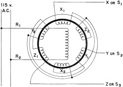
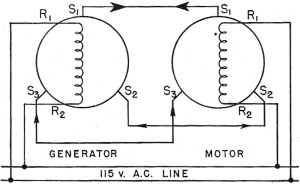
Figure 228. - Synchro windings. Figure 228 is the schematic of a synchro. Notice that the stator winding is just like the winding on a three-phase motor or alternator stator - a three-phase job. The rotor has a single phase winding and is connected to a 60 cycle, 115 v., a-c line. The rotor shaft is coupled to the gyro and turns every time the gyro turns. This synchro is called the generator. At the bridge end of the line, a second synchro repeats the gyro reading. Its rotor is coupled to a repeater compass. This synchro is called the MOTOR. Although these two synchros have different names, they are EXACTLY ALIKE ELECTRICALLY. Both have three-phase windings on their stators and single phase windings on their rotors.
Notice in figure 229 that BOTH rotors are energized from the same single phase a-c line. Also, the two stator windings are connected together in series. It is important that the X winding of the generator be connected to the X winding of the motor. And likewise that the two Y and the two Z windings are each connected together. In synchros the leads from the X, Y, and Z windings are usually marked S1, S2, and S3, And the rotor leads are marked R1 and R2.
Figure 229. - Synchro generator and motor. Now, consider each unit as a transformer - the rotor is the primary and the stator is the secondary. The two rotors are in the same position-say opposite the S1 windings. Both primary fields are cutting the secondary windings and inducing a voltage. But the VOLTAGES are UNABLE to move any CURRENT because they are EQUAL and OPPOSITE. EQUAL because the voltages are induced by duplicate fields and OPPOSITE because they both try to force current OUT on the line connecting the two S1 windings. Figure 229 shows the two voltages meeting head on.
The other S2 and S3 windings are acting just like the S1 winding. Notice that their voltages likewise cancel. Generator and motor voltages balance - zero current flow. The total effect of this is ZERO. Nothing happens - the two rotors remain in their positions opposite the S1 windings.
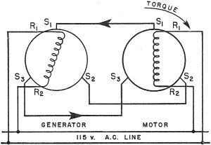
Now the ship changes course. The rotor of the generator synchro is turned by the gyro - say half way to the S3 winding (30°). The two synchro rotors are no longer in the same relative position. And the voltages induced in the two stator windings no longer balance. The generator's S1 voltage is weaker and its S3 voltage is stronger. Current flows from the generator's S3 to the motor's S3 and from the motor's S1 to the generator's S1, Figure 230 shows the two synchros with their rotors in the new position. This time the arrows indicate CURRENT direction. The new conditions are this - both S1 and S3 windings have fields which are trying to pull their rotors back into identical relative positions. The transmitter CANNOT move - the gyro holds its rotor in the new position. But the motor rotor can move. It does just that AND CARRIES THE REPEATER COMPASS WITH IT. The motor rotor moves to the point where all the S1, S2, and S3 voltages balance again and the stator currents become zero. This point is where the transmitter and motor rotors are in identical positions again. The total effect is a rotation of the motor's rotor exactly following the rotation of the transmitter's rotor. You might look at it this ,way-each rotor is a primary inducing a voltage in three secondaries. As long as the three secondary voltages balance against each other, no current flows. But move the transmitter primary and, thereby increase or decrease the voltage on any of its secondaries and current flows. This current flows in both transmitter and motor - their secondaries are connected together. A field is set up by this current and it acts on the motor primary. Actually this is MOTOR ACTION. The motor primary is forced to move by the torque of the motor action. The primary stops moving only' when the torque is again zero. And zero torque is produced only when. no current flows in the secondaries. You know when that happens - at the point where the two primaries are in identical positions. The secondary voltages will then balance against each other.
Figure 230. - Torque produced in a synchro motor. Thus every move of the transmitter's rotor produces torque on the motor's rotor. The motor's rotor, answering this torque, follows every move of the transmitter's rotor. Thus, for every shift of 337 the gyrocompass, a corresponding shift occurs in the bridge repeater. You'll run into synchros of a different type. They have a single phase winding, with a.c. impressed, on the stator. And the rotor has a winding just like the three phase wound rotor. With this type of synchro, you'll have to consider the stator winding as the primary and the rotor winding as the secondary. The leads are numbered differently too - R1, R2, and R3 come from the rotor slip rings and S1 and S2 are the stator leads.
When the rotors of both generator and motor are in the same position, voltages on the R1, R2, and R3 leads balance - no current and no torque. But if the generator rotor is turned, this balance is upset - current flows in the rotor windings and torque is produced. Motor action forces the motor rotor to a balancing position - duplicating the generator rotor's position.
There's nothing electrically new in this type of synchro - it just has the rotor and stator windings reversed. Study it as a transformer and you'll "get it."
AND OTHERS These have been only a few examples of machines and transformer action. When you run into something new, examine the new device for transformer action. It's the easiest way to get the low-down on new equipment. Chapter 21 Quiz
|