|
Electricity - Basic Navy Training Courses NAVPERS 10622 |
|
Here is the "Electricity - Basic Navy Training Courses" (NAVPERS 10622) in its entirety. It should provide one of the Internet's best resources for people seeking a basic electricity course - complete with examples worked out. See copyright. See Table of Contents.
¶ U.S. GOVERNMENT PRINTING OFFICE; 1945 - 618779
CHAPTER 18 What is the most important fact to know when you are filling an automobile tire? The air pressure within the tire, of course. And, how is this air pressure measured? By a "tire gage" - a simple air-pressure METER. Try to fill a tire without a gage. Nine times out of ten the tire is too hard or too soft. The air-pressure meter is your "eye" to "see" and measure air pressure. In a sense, all meters are "eyes" specially developed to see and measure invisible forces and quantities. The speed of a ship is measured by a taffrail log or a tachometer - both are meters. Boiler pressure is read directly from a meter. In gunnery, both range and elevation are calculated by meters. All meters collect data INSIDE a system and deliver it to the "OUTSIDE where it can be used. Meters answer the question, "how much?" In an electrical system, "how much?" is asked about four quantities - CURRENT, VOLTAGE, RESISTANCE, and POWER. And four kinds of meters measure these quantities - ammeters, voltmeters, ohmmeters, and wattmeters. Each meter's name indicates its use. Every conductor, every motor, every circuit of any kind has a RATED current load. Exceed this rated load and you ask for trouble - heat develops, connections melt, and insulation burns. AMMETERS tell you exactly how much current is flowing - they forewarn you of overload. Each insulation has a voltage rating. And 120-volt insulation will not stand 240 volts. It's like trying to put 70 pounds of air pressure in a bicycle tire rated at 35 pounds. Something lets loose. Motors are built to operate at a definite voltage of 110, 220, or 440 volts. If you try to operate a motor above or below its rated voltage, it either "burns out" or gives such poor service that it's useless. VOLTMETERS keep you informed of the voltage of every line and every generator aboard ship. Resistance and power can always be calculated from ammeter and voltmeter readings. R = E/I and P = EI. However, OHMMETERS and WATTMETERS, which read these values directly, are handier - and they are built to do your dividing and multiplying for you.
WHAT METERS DO Meters have been compared to your eyes - remember they are just. about as delicate. A good meter costs much more than a good watch. Every meter is built to measure quantities within a definite range. And, if you want your meters to stay accurate, don't drop them and don't overload them. An outboard motor is a good LITTLE engine, but, it won't drive a destroyer. Neither will a 10-ampere ammeter measure 100 amperes.
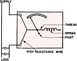
One thing that makes the study of meters easy is the fact that ALL METERS MEASURE CURRENT. Yes, the voltmeter, ohmmeter, and wattmeter all measure current - because the voltage, the resistance, and the power are ALL PROPORTIONAL TO THE CURRENT. The CURRENT in a voltmeter gives an accurate picture of how much VOLTAGE is pushing that current. The CURRENT in an ohmmeter tells you exactly how much RESISTANCE is holding that current back. Power is the product of E and I, and the amount of CURRENT, therefore, controls the amount of power. Although all meters measure current-they are not all calibrated (scaled) in amperes. Each meter has a scale to read the units it is meant to measure. Ammeters read directly in amperes, voltmeters read volts, ohmmeters read ohms, and wattmeters read watts. HOW THEY DO THE JOB Current produces three effects on an electrical circuit. All three effects are used in meter construction. The three current effects are - HEAT, MAGNETISM, and MOTOR ACTION. The STRENGTH of each one of these effects depends on the amount of current. There are three types of meters built - each type measures one of the current effects. And although it is the effect which is measured, the STRENGTH OF THE EFFECT is an accurate gage of the STRENGTH OF THE CURRENT. HOT WIRE METERS The HOT WIRE METERS use the heat-producing effect of current. As current flows in a conductor, the friction produces heat. The stronger the current, the greater the heat. This type meter uses a high resistance wire that expands a great deal when it is heated. When the wire cools, it shrinks back to normal length. Figure 187 shows a hot wire meter. Notice that the high resistance wire has become heated and expanded by the current flowing in it. The slack in the wire allows the spring to pull the indicator needle to the right. In this way, the needle is measuring the expansion of the wire. (Get the idea - heat effect is measured.) And this expansion is proportional to the SQUARE of the current in the Wire.
Figure 187. - Hot wire meter. If the slack in the wire allows the needle to move one-half inch for the first ampere of current, then the scale behind the needle cannot be calibrated in equal spaces. In this particular meter, the scale is calibrated in unequal divisions. But, because the heat produced is proportional to the square of the amount of current, each division stands for the same amount of current. A hot wire meter would have much larger amounts of current calibrated on the right-hand end of the scale. A particular scale might read something like this - 1 ampere, 2 amperes, 3 amperes, 14 amperes, all spaced further apart. The left-hand end is called a CRAMPED or COMPRESSED scale. A.C. and D.C. produce equal amounts of heat per ampere, therefore, the HOT WIRE METERS CAN BE USED ON EITHER A.C. OR D.C. MAGNETIC METERS MAGNETIC METERS make use of the magnetic flux effect of a current traveling in a conductor. There are two general types of magnetic meter - the D'ARSONVAL or MOVABLE COIL type and the MOVABLE IRON type.
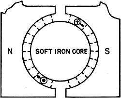
Figure 188. - D'Arsonval type meter. The D'Arsonval type consists of a strong V-shaped, permanent magnet mounted in a stationary frame. Notice, in figure 188, that the pole pieces of this magnet are circular. This shape insures an even distribution of flux from the permanent magnet. In the center of the space between the pole pieces is mounted an iron core - also stationary. This iron core is small so that a small movable coil can turn in the air space between the core and the permanent magnet. The movable coil carries the current' of the circuit, and has the indicator needle attached. When current flows in the coil, it acts like the armature of a motor. The field of the coil reacts with the field of the permanent magnet, producing torque. The action is illustrated in figure 189. Note that the iron core preserves much of the flux of the permanent magnet. In this drawing, the coil is represented by only one turn of wire. Actually the coil contains many turns - 20 or more.
Figure 189. - D'Arsonval action. The feeders for the movable coil are the two spiral springs shown in figure 188. They do two jobs - conduct the current to the coil and ACT AGAINST THE COIL'S TORQUE. Thus, the amount of turning produced is proportional to the combined effect of the torque AND the opposition of these springs. As the current increases; the torque becomes stronger and the amount of turn is greater. The indicator needle is carried across the scale as the coil turns. The scale is a LINEAR " calibration. That is, the divisions are of equal size and represent equal amounts of current. For example, they might read 1, 2, 3, 4, 5 amperes. A linear scale can be used because the amount of magnetic effect or torque produced is DIRECTLY proportional to the strength of the current.
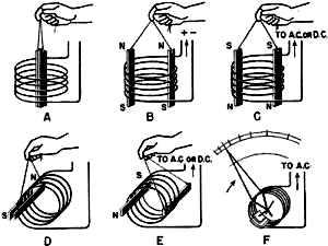
The D'Arsonval type meter is extremely sensitive. In fact, it is the best action to use in the sensitive galvanometer. In order to make full use of the sensitivity and accuracy of this meter, the shaft holding the coil runs in jeweled bearings. Also, the weight of the indicator needle is counterbalanced by a weight threaded on the needle's other end. This cancels any gravitational torque which might be added to the coil's torque. Since this meter depends on motor action - current in one direction - it can be used ONLY ON D.C. The MOVABLE IRON type of meter has one marked advantage over the D'Arsonval type. It can be used on EITHER D.C. or A.C. Follow the movable iron action through each diagram of figure 190. A shows two pieces of iron held in a "dead" coil. No action! B shows what happens when the coil is energized by d.c. The Coil Hand Rule tells you that polarity is induced in the iron as shown. Like poles are produced on adjacent ends of the iron pieces. Repulsion throws the two pieces of iron away from each other. C shows that A.C. produces the same effect - either norths or souths repel with equal force. D is a duplicate of A except that one piece of iron is permanently attached to the inside of the coil. When the coil is energized with a.c. or d.c. as in E, the remaining piece of iron -" free to move-is repelled to the opposite side of the coil.
F is the developed meter as it actually is. The movable piece of iron and the indicator needle are mounted on a jeweled shaft. This shaft permits the movable iron to move only rotationally. The amount of current in the coil determines the amount of repulsion and the amount of rotation. And the amount of rotation controls the indicator needle's. The movable iron meter is a honey - it works on A.C. or D.C. It is almost as sensitive as the D'Arsonval type. And like the D'Arsonval type, the movable iron type has a spiral spring to oppose torque and to restore the needle to the zero point.
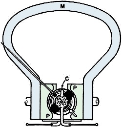
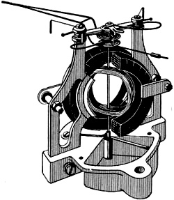
Figure 190. - Movable iron action. DYNAMOMETER METERS The DYNAMOMETER type meter uses the motor action of two fields for measuring current. The first field is set up by two large stationary coils (the heavy coils of figure 191). The second field is set up by a small movable coil pivoted in the center of the large coils. Notice, in figure 191, that this light coil has opposing spiral springs and carries the needle indicator on its shaft. The current to be measured flows in BOTH coils. Since the current in BOTH the stationary and movable coils is the SAME CURRENT, the POLARITIES OF THE COILS ARE ALWAYS THE SAME. Repulsion is produced and the movable coil turns. This meter can be used on d.c. - it acts just like a motor. It also can be used on a.c. since the polarities of both its coils REVERSE TOGETHER on A.C.
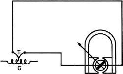
Figure 191. - Dynamometer action. THERMOCOUPLE METERS A fourth type of meter makes use of the voltage produced by a thermocouple - really a heat - type meter. This type meter is illustrated in figure 192. The joined end of the thermocouple T, is wrapped in a coil of high resistance wire C. Then the circuit current is sent through this coil. The resulting heat generates a voltage in the thermocouple proportional to the current which produced the heat. A regular type meter - usually the D'Arsonval type - measures the current produced by the generated voltage. The scale is adjusted and calibrated to read NOT the GENERATED voltage or current but the current of the heating COIL. This meter seems complicated and tricky. It is, but it permits the use of a sensitive D'Arsonval type for measuring a.c. - and that makes it worthwhile.
Figure 192. - Thermocouple meter. WHICH METER WHERE? Why all these types of meters? For the same reason that there are both tug boats and battle- . ships. Each can do some one job best. The D'Arsonval is extremely sensitive but it can be used only on d.c. The movable iron is not as sensitive as the D'Arsonval but it can be used on d.c. or a.c. The hot wire is not particularly sensitive and it takes time to heat the high resistance wire. But it can be used on all d.c. or a.c. circuits including radio circuits. The thermocouple is complicated but it can be used on d.c. or a.c. Also it is a good meter for radio work. It is fairly accurate and it adopts the sensitive D'Arsonval movement to the measurement of a.c. The dynamometer is the most sensitive a.c.-d.c. meter. However, it cannot be used on the high frequencies of radio circuits. As the various types of meters have been pictured, they are operating as galvanometers-sensitive, and carrying the full current of the line. In practical use, any type of meter can be CONNECTED to act as an ammeter, voltmeter, or ohmmeter. The whole problem is to connect the meter to do its job, BUT not "burn out" the meter.
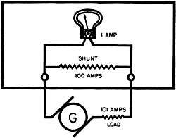
AMMETERS Ammeters measure the CURRENT IN A LINE. Therefore, they must be in series with the line and carryall the line current or a DEFINITE FRACTION SHUNT of the total line current. If the line current is small - a fraction of an ampere, then the meter can usually handle all of it. But seldom do you deal with such small currents. Except in some radio circuits, you'll have to measure currents far too heavy for the light coils of meters. To reduce the current to a safe value in the meter coils a shunt is connected around the meter. This shunt is simply a parallel path carrying most of the current. In this way, the meter carries only a DEFINITE SMALL FRACTION of the total current. Figure 193 shows an ammeter with an INTERNAL shunt.
Figure 193. - Ammeter with internal shunt. Notice that there are two paths for current within the meter. One through the meter coils, the other through the shunt. Say that the resistance of the meter is 1 ohm, the resistance of the shunt is 0.01 ohm, and the total current is 101 amperes. The ratio of current in the meter to current in the shunt is 100 to 1. That is, the meter handles 1 ampere while the shunt carries 100 amperes. The total circuit - meter and shunt - carries the line's current of 101 amperes. Now - just what does the meter read - 1 ampere, 100 amperes, or 101 amperes? It will read 101 amperes BECAUSE the scale has been calibrated for a 101 MULTIPLIER. The ratio of the TOTAL current to the METER current is the multiplier. Internal shunts - the shunts inside a meter case - are fixed. Regardless of what circuit the meter is used in, the shunt is a part of that circuit, and the meter scale is calibrated to read the actual meter current times, the multiplier.
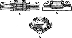
EXTERNAL shunts are shunts connected OUTSIDE the meter box - on the back of switchboards, on the outside of the meter box - or, if portable, any place convenient. Figure 194 shows three types of shunt. A is a switchboard shunt. B is it shunt for mounting on meters. And C is a portable and adjustable shunt. If the shunts are outside the meters, they are easily changed and the meter's range can be in-creased by merely changing a shunt. For example, an ammeter with a range of 0-10 amperes has a resistance of 0.1 ohm. The range is to be increased to 0-100 amperes. What size shunt is required? Just looking at the problem tells you that the multiplier is 10 - because you are increasing the capacity TENFOLD. By doing a little reasoning you know that 1/10th of the current will go through the meter and 9/10ths through the shunt. Therefore, the shunt must have 1/9th as much resistance as the meter - it carries 9 times as much current. The resistance of the shunt is 1/9th of 0.1 ohm or - 0.1 x 1/9 = 0.1/9 = 0.011 ohms. Shunt sizes can be reasoned out this way - just remember that you have a simple two-way parallel circuit. One branch is the meter - the resistance is fixed. The other branch is the shunt - you set this resistance to fit the job. The resistance must below enough so that most of the current will be kept away from the meter. But the resistance of the shunt must also be an EASY FRACTION of the total resistance-because an easy fraction gives you a handy multiplier.
Figure 194. - External shunts. Here is the formula for calculating shunt resistance - Rs = Rm/(N-1) When Rs = the resistance of the shunt;
Rm = the resistance of the meter;
N = the multiplier. Using this formula for the solution of the example above - Rs = Rm/(N-1) Rs = 0.1/(10-1) = 0.1/9 = 0.011 ohm.
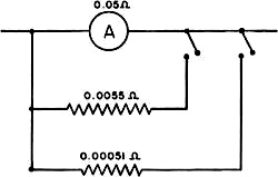
Let's say this ammeter is used to measure an 80 ampere circuit. Here is what happens - 80 amperes are in the line and passing through the meter AND shunt. Because the shunt has only 9/10th the resistance of the meter, the shunt carries 9 times the current of the meter, or 9/10ths of the total current. Hence, the shunt will carry 9/10ths x 80 = 72 amperes and the meter only 8 amperes. And the meter reads only 8 amperes. BUT the multiplier is 10 - so the TOTAL current is the reading (8 amperes) times the multiplier (10) or 8 x 10 = 80 amperes. Remember that ammeters and their shunts must carry the ENTIRE line current. Wherever this cur-rent is reasonably large - 1 ampere or more - a shunt must be used to protect the meter coils. It's true that an ammeter coil could be built to carry the full line current - but it would have to be made of heavy wire. Such a coil would weigh too much - the meter would be cumbersome and not very sensitive. The only ammeter which can carry the full line current is the hot wire type - no coils are used. You will run across ammeters with multiple scales. These are meters using more than one shunt. Figure 195 shows an ammeter with two shunts. This meter has three different scales. The first scale is 0-1 ampere - no shunt is used. The second scale is 0-10 amperes - the first shunt is used. And the third scale is 0-100 amperes - the second shunt is used.
Figure 195. - Multiple shunt ammeter. The resistances of the shunts are shown in the figure. You can see that multipliers of 10 and 100 were used in calculating the resistance of each. Use the formula for finding shunt resistance - prove the values given in figure 195. CAUTION Ammeters are extremely LOW RESISTANCE instruments. They are designed to be connected IN SERIES WITH THE LINE AND ITS LOAD. If you should connect an ammeter across the line, or in parallel with a load, the full line voltage will force a tremendous surge of current through, the delicate coils. The burning action is so fast that line fuses cannot melt in time to save the meter. REMEMBER - AMMETERS ARE ALWAYS CONNECTED IN SERIES WITH A LOAD. VOLTMETERS Look at this formula: E = I/R. It describes the voltage necessary to force a certain current through a certain resistance. Suppose, for a given circuit, the RESISTANCE is CONSTANT. You put an ammeter in the circuit. Every time the CURRENT INCREASES - you know the VOLTAGE must have INCREASED. Every time the CURRENT DECREASES - you know the VOLTAGE must have DECREASED. Remember - the resistance is constant. Exactly what is the ammeter doing? IT IS MEASURING VOLTAGE AS WELL AS CURRENT. And if the scale of the meter reads volts instead of amperes then you have a voltmeter. But wait a minute - it's not quite that simple. In practical circuits, the resistance is seldom constant. However, you can add a resistance that is constant -ALWAYS CONSTANT-by making it a fixed part of the meter. Such a meter is a VOLTMETER.
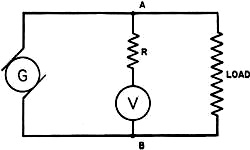
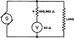
Figure 196. - Voltmeter connection. Look at figure 196 - notice that the meter is in parallel with the load. Now changes in LOAD resistances have no effect on the METER resistance. This is how the voltmeter works - there is a potential difference between points A and B of figure 196 - so much voltage. This voltage forces a SMALL current through the high resistance, R, and then through the meter. The meter acts on this small current. The degree of action depends on the amount of current. And the AMOUNT OF CURRENT IS EXACTLY PROPORTIONAL TO THE VOLTAGE. Therefore, the DEGREE OF ACTION IS PROPORTIONAL TO THE VOLTAGE. And the meter can be calibrated in volts instead of amperes. Notice that the voltmeter must always be connected ACROSS THE LINE. If it were connected in series with any load, the resistance of the load would cut down the current and give a reading too low. Figure out this voltmeter problem - A meter of 50 ohms resistance will give full scale deflection with 0.0005 ampere of current through its coils. How much resistance must be added to the meter circuit in order to use this meter as a 0-500 volt voltmeter? From the 0-500 volt range, you know that full scale deflection must be produced by 500 volts. Also, you know that 0.0005 ampere in the meter coils will give full scale deflection. You can say it either way - both mean the same - full scale deflection by 500 VOLTS or by 0.0005 AMPERE. These two items, line voltage and meter current, tell you how much resistance is needed. It's a simple Ohm's law problem - R = E/I = 500/0.0005 = 1,000,000 ohms. The 1,000,000 ohms is the TOTAL resistance. You need only 1,000,000 minus 50 or 999,950 OHMS ADDITIONAL RESISTANCE. With 1,000,000 ohms resistance, the meter will pass 0.0005 ampere at 500 volts - full deflection. But if the voltage is less - say 200 volts - only 0.0002 ampere passes through the meter coil because - I = E/R = 200/1,000,000 = 0.0002 amp. And 0.0002 ampere is exactly two-fifths of full deflection current (0.000.5 ampere). Therefore, the meter pointer deflects exactly two-fifths of full scale. And on a scale of 0-500 volts, 200 volts would be two-fifths of the way to 500 volts. Every voltage produces its corresponding current. And every cur-rent causes a deflection - and reading - corresponding to the voltage which produced it.
Figure 197. - Voltmeter with series resistance. The complete meter circuit looks like figure 197. The large resistor, R, is usually included INSIDE the voltmeter and the. range is labeled 0-500 volts.
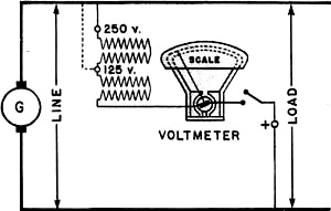
For MULTIPLE SCALE VOLTMETERS, more than one resistor is connected inside the meter. Look at the connections in figure 198. If the meter is connected from + to 250, both resistors are in series with the meter coil and the range is 0-250 volts.
If it is connected from + to 125, only one resistor is in series with the meter coil and the range is 0-125 volts. CAUTION The voltmeter is more rugged than the ammeter - the voltmeter has a high resistance to' protect it. Nevertheless, you can "cook" the windings by trying to measure a voltage higher than the meter's range. BEFORE you connect ANY meter, make certain your instrument has a range high enough to handle the current or voltage of the circuit. When in doubt - USE THE HIGHEST SCALE.
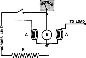
Figure 198. - Multiple scale voltmeter. VOLTMETER-AMMETER METHODS There are four electrical factors in every circuit - current, voltage, resistance and power. There is a special meter to measure each - BUT - you don't need all four meters to know all four facts. With only the ammeter and voltmeter readings, you can CALCULATE both the resistance and the d-c power. Use Ohm's law for resistance - R = E/I and use the Power Equation for power - P = EI Wattmeters and ohmmeters are simply instruments which do the dividing or multiplying for you. Remember that all you need to measure in any d-c circuit are voltage and current. But for a-c power measurement, you must use a wattmeter. WATTMETERS Power is composed of two things-voltage and current. A change in either one changes the power. Therefore, the wattmeter must measure both the current and the voltage. How one meter measures both quantities is shown in figure 199.
Figure 199. - Wattmeter connections. The two coils marked A are stationary-they are the AMMETER part. Notice, they are in series with the load. Coil B is movable and carries the indicator needle - it is the VOLTMETER part. Notice that B is across the line and in series with the resistor, R. The wattmeter is like the other meters except. that there are TWO coils. The strength of coil is determined by the line current. The strength of coil B is determined by the line voltage. Two flux fields are set up - A and B. They exert a force on each other. Coil B is the only coil free to move, and both forces are concentrated on it. Coil B turns, carrying the needle with it. THE AMOUNT IT TURNS IS PROPORTIONAL TO BOTH THE FORCES ACTING ON IT. Therefore, it reads the product of both forces - POWER. Wattmeters having multiple scales usually have their multipliers inside the meter case. It's a tricky job to add external multipliers and then calculate the correct power. If you don't have a correct range wattmeter, the best thing to do is measure current and voltage separately. Then multiply the two readings for the power. THE OHMMETER The OHMMETER is a voltmeter! But - with a very special arrangement of a resistor and a battery. The first type ohmmeter is a voltmeter with a resistance and a battery in SERIES with the meter coil. Figure 200 is a schematic of the series type ohmmeter.
Figure 200. - Series ohmmeter. It works like this - the resistor, R, and the resistance of the meter, Rm, are in series. The battery ( a small dry cell) furnishes just enough voltage to cause full scale deflection of the meter. That is full scale deflection when the test prods are touched together. When any resistance is placed between the test prods, it ADDS RESISTANCE TO THE WHOLE CIRCUIT. Current is reduced and the meter will read LESS than full deflection.
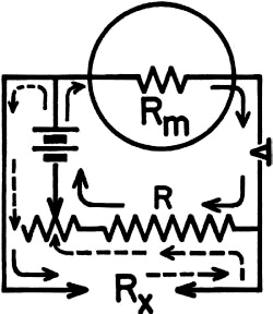
Figure 201. - Shunt ohmmeter. The amount of the reading, less than full deflection, is a measure of the size of the unknown resistance placed between the prods. Thus, this meter reads from right to left. And it must be calibrated that way. The other type ohmmeter also has the battery and resistance in series with a voltmeter. The battery provides just enough voltage for full scale deflection. But in this type - the SHUNT OHMMETER - the unknown resistance is connected in PARALLEL with the meter coil. The best way to get the workings of this meter straight is to follow the circuit in figure 201. The current path through the resistor, R, the meter and the battery is shown by solid arrows. The current path through the resistor; R, the unknown resistance, Rx, and-the battery is shown by broken arrows. Two parallel paths. Apparently they have no effect on each other. But Rx DOES affect the meter circuit and here's the reason. All batteries have internal resistance - therefore, there is a voltage drop INSIDE the battery. Any increase in the internal voltage drop of the battery (IR) is subtracted from the voltage at the battery terminals, thus making the current through the meter less. When Rx is included between the test prods - current through the battery increases - internal IR drop increases - terminal voltage DECREASES and the METER GETS LESS CURRENT. The indicator reads less than full deflection. The lower the Rx, the more current it draws, and the less the deflection. This type ohmmeter reads from left to right. And that's easily proved - if the prods are touched together Rx is practically zero. Almost all of the current is following the broken arrows. And practically no current is left for the meter - it reads almost zero. Which it should - the prods, themselves, have practically zero resistance. The shunt ohmmeter can be explained another way, although it's NOT quite correct. Imagine that the battery can put out just so much current. This current can go two ways - through the meter or through Rx. If Rx is high, most of the current goes through-the meter-high deflection. If Rx is low, most of the current goes through Rx - low deflection. This explanation is not entirely correct BECAUSE the amount of current put out by a battery depends on the total resistance of the circuit AND the terminal voltage. This explanation ignores terminal voltage changes. Both series and shunt ohmmeters use primary cells and these cells lose capacity as they are used. This is the reason for the variable resistance in the ohmmeter circuits. Look at figures 200 and 201 again. Notice the rheostat in series with the resistor and meter coil. This rheostat is used to compensate for any decrease in battery capacity. By increasing or decreasing the rheostat resistance, the meter is set at zero reading before each use. MEGGER The MEGGER is a special instrument for measuring resistance. It's more than just a meter - it contains a small hand generator and a sensitive voltmeter. By following the circuits in figure 202, you will find that the megger is connected very much like a shunt ohmmeter. But with this big difference - the voltage is furnished by the hand generator at the right, not by batteries. This little generator uses permanent magnets for a field. Whenever permanent magnets provide the field for a generator, the machine is called a MAGNETO. The armature is turned by a crank mounted on the side of the megger case.
Figure 202. - Megger connections. Now "why a megger instead of one of the ohm-meters?" Because the megger has a constant voltage - no batteries to wear down. And the megger magneto can be designed to produce, EMFs from 100 volts to 1,000 volts. It will measure a much higher resistance than the ohmmeter. In fact, the megger's name comes from the units it measures - MEGOHMS -millions of ohms. Navy men use meggers constantly to check circuits and cables for grounds. The two megger prods are connected from conductor to ground. This puts the conductor's insulation between the terminals of the megger. Depending on the type of circuit, the insulation should test between 200,000 and 5,000,000 ohms - 1/5 to 5 megohms.
TOUGH ONES When you use meters you're going to run into some tough problems. And at the same time, you're going to run into the special meters built to solve these problems. The catch is this - the meters are pretty complicated! In fact, they're too complicated for this book. But you want to be up on new things - and even if you can't understand all the inner workings, you'll want to know what these special meters WILL DO. SO first a few of the tough questions and then the meters which answer the questions.
QUESTION ONE Suppose you have ONE meter - it doesn't matter whether it's an ammeter, a voltmeter, or an ohmmeter. But, say that it's a D'Arsonval VOLTMETER. And you want to use it as an AMMETER or as an OHMMETER. How do you change the meter to fit your purpose?
THE ANSWER You can reconnect the meter to fit your purpose. If you strip the voltmeter of its series resistance - then it's no longer a voltmeter. It's just a plain D'Arsonval meter. Then by RECONNECTING resistances and batteries, you can make it an AMMETER, a VOLTMETER, or an OHMMETER. And it's not a very hard thing to do - because meters are built with STANDARD RATINGS. This one has a standard full scale deflection with 0.001 ampere through its coil. It's called a "1 milliampere meter." And it requires one volt to force this one milliampere of current through the coil. Now, you can find the resistance of the coil - Ohm's law - I = E/R = 1/0.001 = 1,000 ohms. Since it requires 1 volt to produce full scale deflection of the 1,000 ohm coil, it's a "1,000 ohms per volt" meter. That's TWO STANDARDS for this meter - 1 MILLIAMPERE and 1,000 OHMS PER VOLT. You know everything there is to know about this meter! Full scale deflection is produced by 0.001 ampere through the coil. And 0.001 ampere requires 1 volt because the coil's resistance is 1,000 ohms.
To make it a VOLTMETER with a 0-150 volt range - add enough resistance to limit the current to 0.001 ampere at 150 volts. Ohm's law again - R = 150/0.001 = 150,000 Ω You already have 1,000 ohms in the meter's coil, so just add 149,000 ohms in series to get the 150,00 ohms total. There's another way to find the required resistance. Remember this meter has 1,000 ohms per volt. So 150 volts will require 150 x 1,000 = 150,000 ohms. Again just add 149,000 ohms in series with the coil. To make the meter an AMMETER with a 0-10 ampere range, add a shunt heavy enough to carry 9.999 amperes. The shunt will leave 0.001 ampere of the full 10 amperes for the meter's coil. No strain on figuring out the shunt resistance. The current is 9.999 amperes, and since the shunt is in parallel with the coil, the shunts voltage is the same as the coil's voltage -1 volt. Ohm's law again - R = E/I = 1/9.999 = 0.100 Ω The shunt's resistance is 0.1 ohm. To make the meter an OHMMETER with a 0-infinite ohm range, connect a resistance and a battery in series so that full deflection is produced with no resistance across the terminals. You would use a 1.5 volt flashlight battery. The current must be 0.001 ampere and the voltage is 1.5 volts. Ohm's law again - R = E/I = 1.5/0.001 = 1,500 Ω You already have 1,000 ohms in the meter's coil - so just add 500 ohms in series with the coil to get the 1,500 ohms total. Usually this 500 ohms (or at least a part of it) is in the form of a rheostat. By using a rheostat instead of a fixed resistance, you can adjust the meter to a zero reading when the battery gets weak.
That's THREE meters - out of ONE. And all made by proper resistance and battery connections! You'll see commercial jobs built like this. They're smooth jobs-all the resistances and batteries are inside the meter case. And all you have to do is turn a selector switch to the kind of meter you want. Then read the values off the correct scale. QUESTION TWO What are you going to do when you have to test the voltage drop across a low current circuit? Say the voltage drop across a radio current limiting resistor. The resistance is 100,000 ohms. The current is 1 milliampere so the voltage is -
E = IR = 0.001 x 100,000 = 100 volts If you used the "1,000 ohms per volt" meter just studied, this is what would happen. You would add 99,000 ohms to the meter to give it a 0-100 volt. range. Then you'd connect it across the resistor to measure the voltage. Now you have two parallel paths. Each has 100,000 ohms resistance. One is the meter, the other is the current limiting resistor. And you only have one milliampere of current for both. The one milliampere splits up - half to each path. And THE METER READS ONLY 50 volts, because it's only getting one-half milliampere. In short - you have a reading that's far from right - only one-half of what it should be. THE ANSWER There are two answers. The first is - use a more sensitive meter. Use a meter with "20,000 ohms per volt." That means much finer and more expensive winding on the coil-a much better meter. Then the meter, instead of needing 1 milliampere for full scale deflection, would need only 0.05 milliampere for full scale deflection. ALWAYS USE A METER WITH A SENSITIVITY HIGH ENOUGH FOR THE JOB. The second answer is - use a vacuum tube meter. These vacuum tube meters are tops! They only draw millionths of an ampere from the tested circuit. And they have internal resistances and batteries for connecting as a voltmeter, a milliammeter, or an ohmmeter. All you have to do is adjust a selector switch for the kind of meter you want. Then adjust another selector switch for the range. And right here is one of the best things about a vacuum tube meter - IT'S PRACTICALLY IMPOSSIBLE TO BURN 'EM UP. They're designed so that you can't overload them more than 20 percent which won't hurt the meter. Each meter has an instruction book for its particular connections. Reading this book will give you the low-down on the instrument. Another good thing about the vacuum tube meter - it has no frequency error up to about 20,000 cycles. You'll find that ordinary 60 cycle meters start to cut up and give you foul readings on anything over 80 or 85 cycles. QUESTION THREE How can you use a d-c D'Arsonval meter on a.c.? This sounds like a good idea-because the D'Arsonval movement is sensitive and it reacts much faster than the heat-effect a-c meters. THE ANSWER Rectify the a.c. so it can be fed as d.c. into the meter. You already know about one kind of rectifier - the commutator. But a different kind of rectifier is used for meters. It's the COPPER OXIDE RECTIFIER. Here is the way it works. Two disks are bolted together - one is copper, coated with copper oxide, and the other is lead. The unit looks like two washers about 1-1/2 inches in diameter, bolted together. This unit is inserted in the a-c line to the meter - it becomes part of the circuit. When a.c. flows, ONLY THE CURRENT FROM COPPER TO COPPER OXIDE IS PASSED. The current in the opposite direction, from oxide to copper, is stopped - eliminated. Thus the rectifier passes all the current in one direction, but it stops all the current in the opposite direction. It works like the check valve in a water intake pipe. The meter gets current in only one direction. So its torque is in only one direction. However, the d.c. fed to the meter is PULSATING - the meter must have a SPECIAL SCALE. That means that you can't just use ANY d-c meter with a rectifier. But you'll find that many of your a-c meters are actually d-c jobs with copper oxide rectifiers and special scales. The SELENIUM OXIDE RECTIFIER is another type of rectifier. You'll find that it works the same way as the copper oxide type. Construction and rectifying effects are the same for both rectifiers. QUESTION FOUR How can you get an actual picture of the a-c wave form? You'll need that picture when you're paralleling alternators, when you're testing and tuning radio circuits, and when you're testing a.c. circuits for power. THE ANSWER An oscilloscope is the answer. This instrument uses a vacuum tube and a fluorescent screen to re-produce the wave form of a.c. By proper connections, the oscilloscope screen will give you the curves of voltage and current for any circuit. The curves tell you the maximum voltage, or any instantaneous value. And by connecting TWO circuits you can get the phasing between TWO voltages or between a voltage and its current. You'll learn a lot more about these special meters as you get into the books for your own rating. But now, at least, you know something about what they can do. Don't try to re-design 'em - keep out of their innards. These special jobs cost plenty, and you'll really be SNAFU if you foul one up! READING METERS Meters are tops in sensitivity and accuracy - but all the accuracy of a good meter can be wasted by reading it wrong. There is only one way to read a meter right. And that's by facing the scale squarely. If your eyes are off to one side, you see the needle at an angle to the scale. The needle seems to be where it isn't!
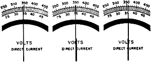
Figure 203 shows incorrect meter reading. Imagine your eyes at an angle above these meters. First, far to the right, then only a little to the right, and finally to the left of the needle. In each position an error is introduced - as much as 10 volts. There is no sense in using a good meter if CARELESS READING gives an INACCURATE MEASUREMENT.
Figure 203. - lncorrect meter reading. Here is another way to foul up a good meter - stand it on its head! Every meter is built to be used in ONE position - either upright, flat, or mounted in a switchboard. The meter's indicator needle is balanced for its correct position. If you use it in an incorrect position, the needle's weight will pull it off the correct reading. Here's a good tip - an UNCONNECTED METER will read ZERO when it's in the correct POSITION for reading. PROFICIENCY SAVER FINALLY, here is a repeat - but it's worth it both to YOU and to the NAVY. CONNECT YOUR METERS PROPERLY! USE METERS OF THE CORRECT RANGE! Know how to connect properly ALL the meters in a circuit. Keep your connections in mind - it may save a 4.0 for you! Chapter 18 Quiz
|