|
Electricity - Basic Navy Training Courses NAVPERS 10622 |
||||||||||
|
Here is the "Electricity - Basic Navy Training Courses" (NAVPERS 10622) in its entirety. It should provide one of the Internet's best resources for people seeking a basic electricity course - complete with examples worked out. See copyright. See Table of Contents.
¶ U.S. GOVERNMENT PRINTING OFFICE; 1945 - 618779
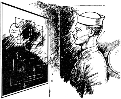
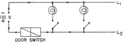
CHAPTER 10 Many circuits are neither SIMPLE series nor SIMPLE parallel. They are COMBINATIONS of simple circuits. Fortunately, it is easy to recognize the series or parallel connections within the combinations by a few simple rules. SERIES CONNECTIONS HAVE - 1. Only one path. 2. Only one conductor connected to a terminal. 3. All the current of one part passing through the other part. PARALLEL CONNECTIONS HAVE - 1. More than one path. 2. More than one conductor connected to a terminal. 3. Divided currents. The best way to understand the complicated series-parallel circuits is to analyze them part by part, or section by section. In this way, the correct circuit law can be used to analyze each part. First, spot your series connections, and then locate the parallels. The balance of this chapter consists of a number of circuits. They illustrate the important problems you will meet in actual circuits. Go through each step carefully-he sure you understand it. If you get stuck, you'll probably find that you've forgotten one of the laws given in Chapters 6, 7, 8 or 9. To help you, all these laws are brought together in a table at the end of this chapter. Turn back to the table if you need help. Remember, the important thing is to KNOW. You don't really know that you KNOW unless you test yourself. When you have finished going over the examples, try working them yourself without reference to this book. After you've finished each example, check your answers and methods against the answers and methods given here. EXAMPLE 1- During war, ships must travel blacked out. No lights show except those used for communication and as formation guides. These lights are screened to 'show only in one direction. Imagine a lighted compartment with a door or hatch opened accidentally-a beautiful target! To guard against any such accident, doors and hatches opening to exposed decks are equipped with door-switches. Door-switches open the lighting circuit of the compartment so that the lights are turned off every time the door is opened. Draw the schematic diagram for wiring a compartment with two overhead lights, separately con-trolled, and with a door-switch. Trace this circuit (figure 56) from - to +. Following the arrows and assuming that all switches are closed, current leaves the negative terminal of the source, flows along L1 (Line 1) to the first light terminal. Here the current divides (did you spot a parallel connection?) - part goes to light No. 1 and part goes to light No.2. (You can determine how much current goes to each light if you know the voltage and resistance - I = E/R). The current passes through the two lights and enters L2 then through L2 and back to the positive terminal of the source.
Figure 56. - Compartment schematic diagram. Try opening switch No. 1. What happens? The circuit through light No. 1 is opened, BUT the circuit through light No. 2 is undisturbed. Try the same with switch No. 2. This switch affects only light No. 2. Switch No.1 is IN SERIES WITH light No.1 and thereby CONTROLS light No. 1. But switch No. 1 is IN PARALLEL WITH light No. 2 and CANNOT control light No. 2. Now open the door-switch. This switch is in series with BOTH lights and CONTROLS both lights. Ask yourself this question, "Does ALL the current of light No. 2 go through the door-switch?" The answer is "YES." And whenever the answer to this question is 'yes' - the two devices are in series.
EXAMPLE 2 - Aboard ship you will have a ship's service generator. This generator furnishes the power for all electrical circuits except propulsion. The generated power is fed through a main switch-board, then through lighting panels, interior communication panels, etc., and to feeder boxes and branch feeder boxes. And finally, to the power outlets - lights, heaters, and telephones.
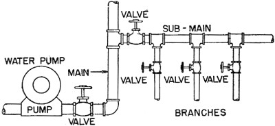
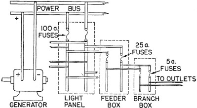
Figure 57. - Water distribution. These ship's distribution systems are a lot like the water distribution systems of small towns. Look at figures 57 and 58 and compare the branching methods .. In figure 58 start at the power outlet-trace backwards to the power bus. (A BUS is simply a very large conductor-usually a bar of copper.) Notice that the fuses PROTECTING each line and box are in SERIES with the load. And of course, switches controlling each load would be in series with that load. If you start tracing at the bus, you will notice that the "FEEDING-OUT" or branching is done by PARALLEL connections. Start tracing from the negative bus and go through the complete circuit of the outlet. How many times is this circuit protected by fuses? The reason for this multiple protection is simple. Each fuse has a capacity which just fits the circuit it protects. For instance, the branch box has 5-ampere fuses because the circuit from branch box to outlet is only large enough to handle 5 amperes. The feeder box is fused for 25 amperes because the circuit from feeder box to branch box will stand only 25 amperes. Each fuse protects its own circuit from overload or short circuit damage.
Figure 58. - Electrical distribution. EXAMPLE 3 - The electrical power to a Navy searchlight must do four things-
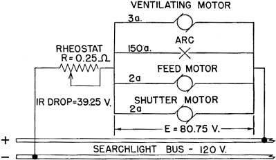
1. Furnish an arc between the carbon electrodes. 2. Run the feed motor. 3. Run the ventilating fan motor. 4. Run the shutter motor. Power is furnished to each of these loads by means of a four-branch parallel circuit. Figure 59 is a simplified diagram of the searchlight circuit. In addition to the loads, there is a rheostat (an adjustable resistance) in series with the parallel group. This is necessary to reduce the ship's voltage from about 120 volts to about 80 volts for searchlight operation. In figure 59 the current is labeled for each load. (1) What is ,the voltage drop across the rheostat? (2) What is the voltage used across each branch of the parallel? (3) What is the resistance of each branch of the parallel? (4) What is the total resistance?
Figure 59. - Simplified searchlight diagram. (1) The rheostat is in series with the rest of the circuit, therefore, it carries all the current of the circuit - It = I1 + l2 + I3, etc. It = 150 + 2 + 2 + 3 = 157 amps. The voltage drop of this rheostat is E = IR = 157 X 0.25 = 39.25 volts. (2) The parallel group is in series with the rheostat, therefore adding the voltages of the group and the rheostat together gives the total voltage. Et = E1 + E2 + E3, etc. 120 = 39.25 + E2 E2 = 120 - 39.25 = 80.75 v. Which means that the voltage drop across the rheostat is 39.25 volts and the drop across EACH branch of the parallel is 80.75 volts. You might look at it this way - you have 120 volts (ship's service) to use in forcing 157 amperes through the complete circuit. The rheostat used up 39.25 volts of this 120. Which leaves 80.75 volts for the balance of the circuit - the parallel group. (3) The resistance of each branch of the parallel appears to be - (arc) R1 = E1/I1 = 80.75/150 = 0.54 ohm. (feed and shutter motors) R2 =E2/I2 = 80.75/2 = 40.38 ohms each. (ventilating fan motor) R3 = E3/I3 = 80.75/3 = 26.92 ohms. Notice in these calculations, that the DIFFERENT, RESISTANCES LIMIT the current to DIFFERENT VALUES for a particular load. (4) The total resistance can be calculated by two methods - Rt = Et/It = 120/157 = 0.77 ohm. OR the resistance for the parallel group is - 1/Rt = 1/R1 + 1/R2 + 1/R3 etc. 1/Rt = 1/0.54 + 1/40.38 + 1/40.38 + 1/26.92 Rt = 0.52 ohm. (of parallel group only) add this to the resistance of the rheostat which is in series - Rt = R1 + R2 + R3, etc. Rt = 0.52 + 0.25 = 0.77 ohm.
It is important that you see how much EASIER it is to find TOTAL RESISTANCE BY OHM'S LAW. EXAMPLE 4 - You know that searchlights are bright-but how much power do they consume? In the searchlight of Example 3, the ARC ITSELF used 80.75 volts and passes 150 amperes. Therefore, its power is - P = EI P = 80.75 x 150 = 12,112.5, say 12,110 watts.
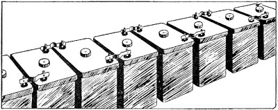
And the total power consumed by the light and its apparatus is - P = EI P = 120 x 157 = 18,840 watts. This is approximately the same amount of power as consumed by a 20-hp motor. SOME LIGHT! EXAMPLE 5 - The operating voltage of a sub-marine's motors is 120 volts at cruising speed. This voltage must come from batteries of the lead-acid type. But this type of storage battery produces only 2 volts per cell. How is an emf of 120 volts produced by cells which themselves produce only 2 volts each? Look at the laws of voltage in the series and the parallel circuits - Et = E1 + E2 + E3, etc. (SERIES) Et = E1 = E2 = E3, etc. (PARALLEL) It is evident that in the series connection, voltages will add. Two cells of 2 volts in series would add, giving 4 volts. And ten cells in series would give 20 volts. To produce the 120 volts needed by the sub's motors requires 60 cells in series. A part of such a battery is shown in figure 60. All batteries store only a certain amount of energy - the exact amount is known as their CAPACITY. Capacity is measured in units of AMPERE-HOURS - the number of amperes which can flow for a certain number of hours before the battery is discharged. For example, a battery having a capacity of 100 ampere-hours will deliver a current of 10 amperes for 10 hours (10 x 10 = 100) or 5 amperes for 20 hours (5 x 20 = 100) or 50 amperes for 2 hours (50 x 2 = 100) before it is discharged. Say that the sub's motors require a current of 200 amperes at 120 volts. This would exhaust a 1,000 ampere-hour battery in 5 hours. But by using two batteries in PARALLEL the drain on each battery is only 100 amperes - It = I1 + I2
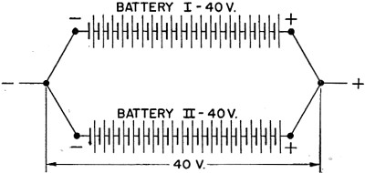
Figure 60. - Cells in series. Where It = 200 amperes, I1 and I2 are only 100 amperes each. Figure 61 shows two batteries of 20 cells - the cells are in SERIES and the two batteries are in PARALLEL. Remember that CELLS IN SERIES INCREASE THE VOLTAGE and CELLS IN PARALLEL INCREASE THE CURRENT. EXAMPLE 6 - Three vacuum tube filaments rated at 0.3 ampere and 6.3 volts must be operated on a 110-volt line. Obviously, the voltage is too HIGH. Even connecting the tubes in series - Et = E1 + E2 + E3 110 = 36.67 + 36.67 + 36.67 gives a voltage of 36.67 volts per unit whereas each unit is designed for only 6.3 volts. This means applying about six times the rated voltage to each tube - they would burn out in a split second. A series resistance will have to be added to the circuit to use up some of the excess voltage. The question is - how MUCH resistance? You have a circuit involving 110 volts and you must LIMIT the current by a resistor to 0.3 ampere.
Figure 61. - Cells in series-parallel. Therefore, you will need a total of - R = E/I = 110/0.3 = 366.67 ohms of resistance.
You already have - R = E/I = 6.3/0.3 = 21 ohms of resistance in each tube. If they are connected in series, you have a total resistance of - Rt = R1 + R2 + R3 Rt = 21 + 21 + 21 = 63 ohms.
for the tubes. If the tubes furnish 63 ohms out of a total requirement of 366.67 ohms, the balance, R2, is found to be - Rt = R1 + R2
366.67 = 63 + R2 R2 = 366.67 - 63 = 303.67 ohms.
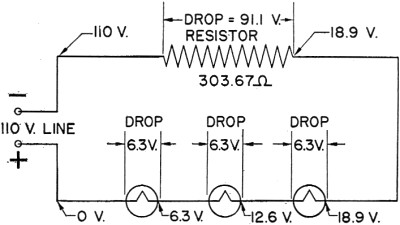
This resistance would have to be furnished by the resistor. The completed circuit would look like figure 62. Notice that the voltage is labeled at a number of points in figure 62. This shows that the voltage drops as the current goes through each successive load. In other words, some voltage is used up in pushing the current through each resistance. The voltage drop in each case, is the difference in voltage between the two points.
Figure 62. - Example 6 - Series. You can prove this circuit. The voltage drop (often called IR drop) across the resistor is - E = IR = 0.3 x 303.67 = 91.1 volts leaving E2, which is found by the formula - Et = E1 + E2
Et = 91.1 + E2 = 18.9 volts
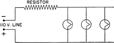
This is the total for the three tubes. They are in series so each uses one-third of this 18.9 volts, or 18.9/3 = 6.3 v. which is the rated voltage. PRACTICE For practice, try to set up this circuit with the tubes in parallel, and a limiting resistor in series. Your circuit should look like figure 63.
Figure 63. - Example 6 - Parallel. BEFORE OR AFTER Perhaps you are wondering if it makes any difference whether a limiting resistor comes BEFORE or AFTER the load. Think about a garden hose. Does it make any difference which valve you operate - the one at the meter, or the one at the side of the house, or the one in the nozzle of the hose? Partially closing anyone of these valves will limit the amount of water flowing through the hose. Likewise, placing a resistance any place in a circuit will limit the current through every load that is in series with the resistance. CIRCUIT LAWS
Chapter 10 Quiz
|
||||||||||